 ENG
ENG  English
 русский
 Español
 Português
 عربى
عربى


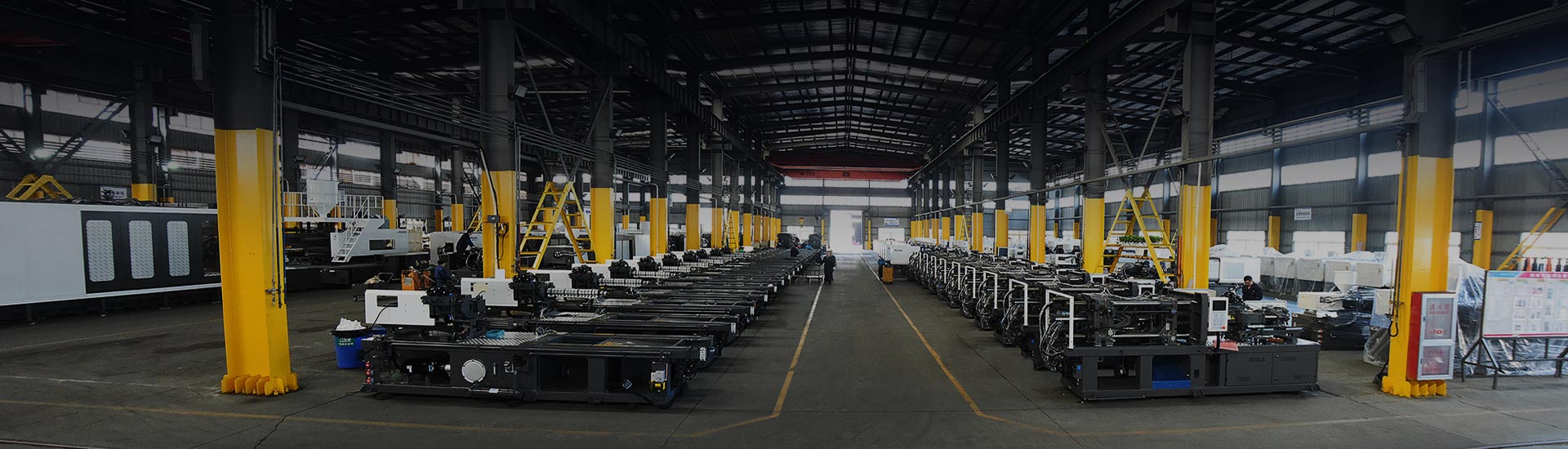
An enclosure looked perfect in the CAD review. The mold shop still rejected it: a 5 mm wall behind the display bezel, zero draft on a 60 mm deep sidewall, and sharp internal corners at every rib base. The result was predictable — sink marks on the visible face, drag lines during ejection, and rework before the first trial. Most molding problems are actually decided before steel is cut.
The basic process of injection molding — melt, inject, pack, cool, eject — places tight demands on every feature of the part. Wall thickness, draft, ribs, parting lines, gating and material shrinkage form the shared language between the part designer and the toolmaker. Nail these basics and the mold becomes a reliable manufacturing asset; miss them and the debugging begins at the press.
Content
- 1 Why the design phase fixes your cost structure
- 2 Mold anatomy: what an injection mold contains
- 3 Wall thickness: the starting point of every mold design
- 4 Draft angles: the non-negotiable release feature
- 5 Ribs, bosses and internal radii
- 6 Undercuts and parting lines: avoid hidden tooling cost
- 7 Gates and ejection: how the part fills and releases
- 8 Match the mold design to the molding machine
- 9 A defect-focused design review
- 10 Final mold design checklist
- 11 Frequently asked questions
- 11.1 What is injection mold design?
- 11.2 What draft angle should I use for injection molding?
- 11.3 What is the recommended wall thickness for injection molding?
- 11.4 What causes sink marks in injection molding?
- 11.5 How much shrinkage should be allowed in an injection mold?
- 11.6 How do I choose an injection molding machine for my mold?
Why the design phase fixes your cost structure
Tooling cost, cycle time and part consistency are largely fixed on the drawing board. A small change at concept stage is cheap; the same change during mass production is expensive. A widely used design-for-manufacturing rule of thumb in the plastics industry puts the multiplier at 30 to 100 times once the mold is running in production. Mold design is therefore a cost-control activity, not just an engineering exercise. Spending the extra design hours early — on gate position, core-outs, draft and tolerance reviews — is the standard way to avoid five-figure mold revisions and expensive lost production time.
Mold anatomy: what an injection mold contains
An injection mold is a precision assembly that forms the exterior of the part with its cavity and the interior with its core. These two halves meet at the parting line, and every detail around them matters. The sprue bushing and runner deliver melt to the cavity through a gate; cooling channels remove heat; ejector pins push the part off the core after the mold opens. Understanding this structure helps the designer treat the part as half of the tool, not as a standalone object.
Wall thickness: the starting point of every mold design
Uniform wall thickness is the most repeated rule in injection molding for a reason: melt flows fastest through thin regions and stays hot longer in thick ones. If adjacent walls differ by more than about 10–15 percent, shrinkage becomes uneven, and the molded part warps or sinks. Keep the nominal wall in the range recommended for the resin, and where a transition cannot be avoided, taper it over at least three times the thickness step.
| Material | Usable range (mm) | Preferred nominal (mm) | Flow-length-to-wall guidance |
|---|---|---|---|
| PP | 0.8–3.8 | 1.5–2.5 | Readily fills thin sections |
| ABS | 1.2–3.5 | 2.0–3.0 | Keep under 2.5 mm for tight tolerances |
| PC | 1.0–4.0 | 2.0–3.0 | High melt flow resistance |
| PA6 | 0.8–3.8 | 1.5–3.0 | Good flow; drying is critical |
| POM | 0.8–3.2 | 1.5–2.5 | Good flow, high shrinkage |
| PS | 1.0–4.0 | 1.5–3.0 | Brittle; avoid sharp notches |
Shrinkage rises with crystallinity, which is why PP, PA6 and POM need larger dimensional allowances than ABS or PC. The ranges above are typical values reported in resin supplier datasheets.
Draft angles: the non-negotiable release feature
Draft is the taper on mold-facing walls that allows the part to release. Without it, the molded part sticks to the steel, ejection pressure rises, and drag marks or deformed parts follow. The rule is simple: at least 0.5°–1° per side on a polished surface, and more when texture is specified, because the rough surface grips the resin. Deep ribs and cores need the upper end of the range. The SPI/SPE finish class is the reference most toolmakers use to agree on draft values.
| SPI/SPE finish class | Surface condition | Draft per side |
|---|---|---|
| SPI A | Mirror polish | 0.5°–1° |
| SPI B | Fine polish | 1°–1.5° |
| SPI C | Paper stone finish | 1.5°–2° |
| SPI D | Dry blast / light texture | 2°–3° |
| Deep texture | Coarse blast or etch | 3°–5° or more |
Ribs, bosses and internal radii
Ribs exist to add stiffness without thickening a wall. Standard practice puts the rib base at 50–60 percent of the nominal wall, with a base fillet of 0.25–0.4 times the wall, and a rib height up to roughly three times the rib-base width. Core out thick bosses the same way: an outer diameter close to twice the inner diameter, generous draft, and gussets where side loads occur. Internal corners should always carry a radius; a sharp corner concentrates stress and slows melt flow. These small details are exactly where sink marks and stress cracking are born.
An undercut is any feature that traps the part in the tool. Snap hooks, side holes and internal threads all demand moving mechanisms — slides, lifters or collapsible cores — each adding tooling cost, wear points and maintenance. The cheapest undercut is the one designed out: orient features parallel to the opening direction, or let a side hole become an open slot along the parting line. Multi-material parts, for instance a soft-touch handle over a rigid core, avoid a secondary assembly step when produced in a two-color machine, so the mold concept changes accordingly and should be reviewed early.
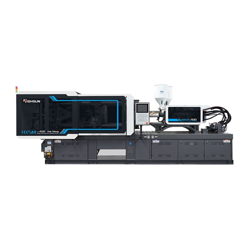
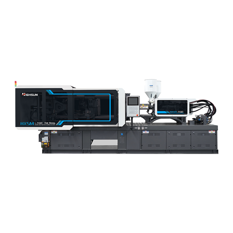 HXS160 Two-Color Injection Molding Machine for Multi-Material PartsThis two-color machine suits the article's discussion of multi-material parts that avoid secondary assembly. Its dual injection units enable integrated soft-touch handles or combined colors in one molding cycle.View Product →
Gates and ejection: how the part fills and releases
The gate is the last narrow channel before the cavity. Its location controls weld lines, packing and appearance: put the gate on the thickest wall so the melt packs fully, and hide it behind a cosmetic face whenever possible. Submarine gates trim themselves; edge gates are easy to machine but leave a visible vestige. Ejector pins, similarly, need bearing area — place them on drafted, flat surfaces and away from visible faces so the part does not deform or become marked. Consistent shot-to-shot pressure is what makes these design assumptions hold, which is why a servo machine with repeatable injection control is the standard choice for precision molds.
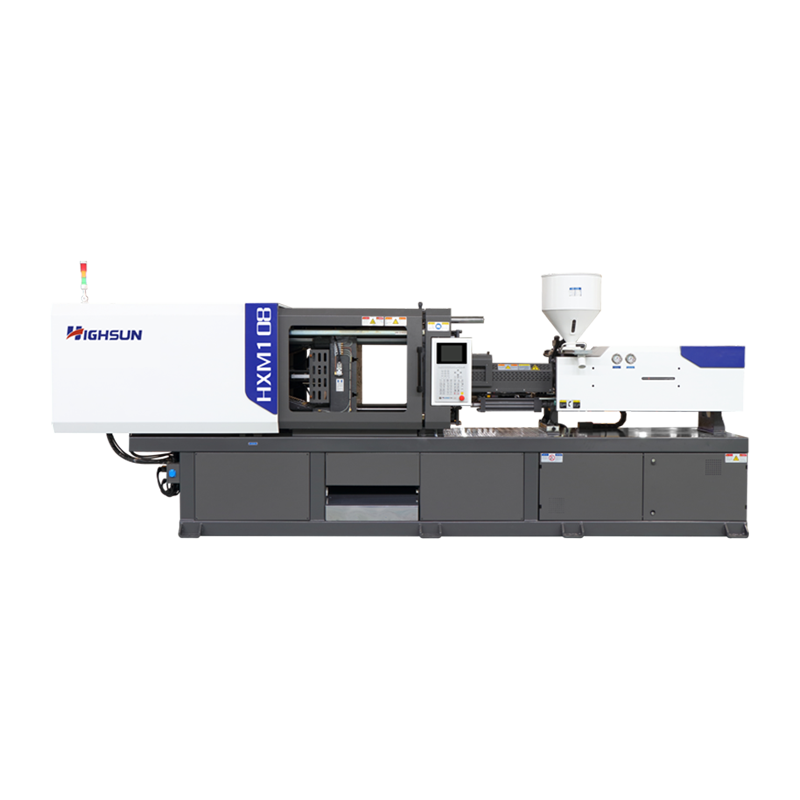 HXM108 Servo Injection Molding Machine with Energy-Saving Precision ControlThe text highlights repeatable shot-to-shot pressure for precision molds. This servo machine offers closed-loop process control and 30-50% energy savings, aligning with the need for consistent clamping and injection performance.View Product →
Match the mold design to the molding machine
Mold design and machine selection must be reviewed together. The clamping force comes from the projected part area multiplied by the cavity pressure, which for engineering resins is in the range of 300 to 700 bar. A thin-wall product of 0.5–1.0 mm, for example a food container, fills reliably only on a high-speed machine with fast injection velocity and quick pressure response. Large-area parts, conversely, need a large platen and high clamp tonnage. Before the mold base is ordered, confirm the shot weight, injection pressure, tie-bar spacing and mold height against the chosen machine; the investment in the mold is too large to leave to assumptions. For application-specific machine configurations, review the industrial applications and available machine families before finalizing the mold.
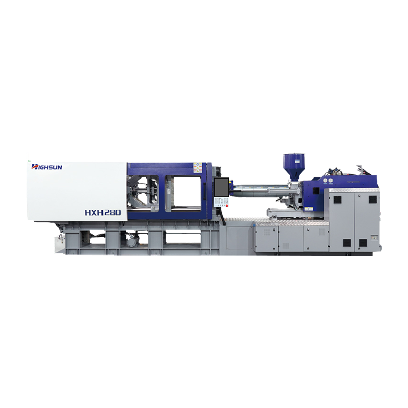 HXH280 High-Speed Injection Molding Machine for Thin-Wall PartsThe article mentions thin-wall products like food containers needing fast fill. This high-speed machine's intelligent full closed-loop control and millisecond pressure adjustments support reliable molding of such demanding geometries.View Product →
A defect-focused design review
The fastest way to validate an injection mold design is to read the geometry against the defects it could generate. The table below summarizes the most common issues and the design-stage corrections available before the mold is cut.
| Defect | Primary design cause | Design fix at the drawing stage |
|---|---|---|
| Sink marks | Local wall thickness too high | Core out thick sections, add ribs |
| Warpage | Non-uniform wall or unbalanced fill | Equalize thickness, balance gate and runner |
| Short shots | Wall too thin relative to flow length | Increase thickness or relocate gate |
| Weld lines | Two flow fronts meet and cool | Move gate, add venting, fill from one side |
| Drag marks | Insufficient draft or rough finish | Increase draft, polish the affected surface |
| Flash | Parting line not flat or insufficient clamp force | Keep parting line flat, verify clamp force |
Final mold design checklist
- Keep wall thickness uniform; hold local variations under roughly 15 percent.
- Apply at least 1° draft per side on polished surfaces, more on textured ones.
- Fillet internal corners with a radius of at least 25 percent of the wall thickness.
- Use ribs of 50–60 percent nominal wall thickness instead of thickening structural walls.
- Core out bosses; keep boss outer diameter close to twice the inner diameter.
- Review all undercuts; minimize slides and lifters or open them through the parting line.
- Place the parting line on a flat, non-cosmetic plane.
- Gate the thickest wall at the least visible location.
- Provide flat, drafted lands for ejector pins.
- Check material shrinkage allowance and mold-machine compatibility.
Frequently asked questions
What is injection mold design?
Injection mold design is the engineering of the tool that shapes molten plastic into finished parts. It defines cavity and core geometry, the parting line, gating, cooling and ejection, and it determines the part's quality, cycle time and unit cost.
What draft angle should I use for injection molding?
Use at least 1° per side for polished surfaces. Light textures need 1.5° to 2°, deep textures 3° to 5° or more. Deep ribs and bosses should stay at the upper end of the range. Confirm the SPI/SPE finish class with the toolmaker before locking the CAD geometry.
What is the recommended wall thickness for injection molding?
Typical nominal walls fall between 0.8 mm and 4.0 mm depending on the resin. PP, PA6 and POM fill thinner sections; PC and ABS are usually kept between 1.5 mm and 3.5 mm. Uniform thickness matters more than the absolute value — keep transitions gradual.
What causes sink marks in injection molding?
Sink marks happen where a thick section cools and shrinks after the surface has frozen. Avoid solid thick bosses by coring them out, use ribs instead of thick walls, keep the rib base at 50–60 percent of nominal wall, and place the gate near thick regions so packing can compensate.
How much shrinkage should be allowed in an injection mold?
Shrinkage depends on the resin: PP is typically 1.0–2.5%, POM 1.5–2.5%, PA6 0.7–1.8%, ABS 0.4–0.7%, PC 0.5–0.7%. Cavity dimensions are calculated from the part dimension adjusted by the shrinkage factor, then refined during mold trials. Directional shrinkage and packing pressure shift the final value.
How do I choose an injection molding machine for my mold?
Calculate the required clamp force from the projected part area times the cavity pressure (roughly 300–700 bar), then verify shot weight, injection pressure, tie-bar spacing and mold height. Thin-wall molds need a high-speed machine; large molds need a large two-platen or high-tonnage machine.
 +86-188 6861 6288
 haixiong@highsun-machinery.com
 No.36 Yongjiang South Road, Beilun District. Ningbo City, 315800, China