 ENG
ENG  English
 русский
 Español
 Português
 عربى
عربى


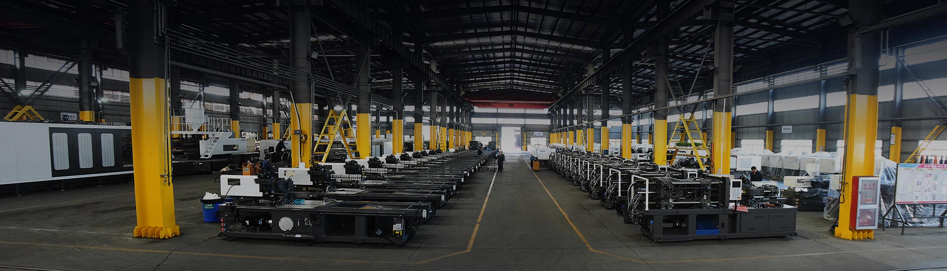
Picture a 16-cavity tool for a 1.2 mm thin-wall food container. Two mold shops quote the same steel grade, the same hot runner make and the same ten-week lead time. One tool settles into a 9-second cycle with scrap under half a percent. The other needs 12 seconds and spends the shift chasing flash. The molding machine is identical. What differs is how the mold was designed.
The short version: when you design injection molds, you decide most of what the part will cost for the next five years, and the priciest mistakes happen in the first two weeks. Wall thickness, draft, steel selection, gate position, runner size, cooling layout and ejection are all connected. Change a wall thickness after the cavity block is hardened and you buy a new insert. Change it during the CAD review and it costs an afternoon of engineering time.
Process guides typically put cooling at roughly half to two-thirds of the total cycle, with packing, injection and mold motion making up the remainder. That single fact explains why cooling layout, not injection speed, is usually the first place to look when a tool refuses to hit its quoted cycle.
Approximate share of a molding cycle. Actual ranges shift with wall thickness, resin and machine settings.
Content
- 1 Start With the Part, Not the Mold
- 2 Steel Choice and the Plate Stack
- 3 Gates, Runners and Venting
- 4 Cooling Layout and Ejection Design
- 5 Match the Mold to the Machine Before You Cut Steel
- 6 Large Molds Need a Different Set of Habits
- 7 Defects That Trace Back to Mold Design
- 8 Frequently Asked Questions About Designing Injection Molds
- 8.1 Q1. What matters most when designing injection molds?
- 8.2 Q2. How many cavities should an injection mold have?
- 8.3 Q3. What draft angle do injection molded parts need?
- 8.4 Q4. How does mold design affect injection molding cycle time?
- 8.5 Q5. Which mold steel is best for high-volume production?
- 8.6 Q6. Can one mold design run on different injection molding machine brands?
Start With the Part, Not the Mold
A cavity block cannot rescue a part that was drawn for appearance instead of flow. Before any mold geometry is modeled, four part-level rules carry most of the weight.
- Uniform wall thickness. Thick sections freeze later than thin ones, which produces sink marks, voids and warpage. Where stiffness is needed, add ribs at roughly 50 to 60 percent of the nominal wall instead of thickening the wall itself.
- Draft. Vertical faces drag against steel during ejection and scuff the part. Common guidance is 0.5 to 1 degree on smooth surfaces, with extra draft for textured faces and deep cores.
- Radii. Sharp internal corners concentrate stress and throttle the melt. An inside radius of at least half the wall thickness is a standard starting point.
- Undercuts. Every undercut adds a side action, a lifter or a collapsible core, plus maintenance. Some are unavoidable, but each one deserves a second question.
Wall thickness also drives cycle time more than any other single variable, because it follows a square relationship described in standard heat-transfer references used across the molding industry.
Cooling time scales with the square of wall thickness, so doubling a wall roughly quadruples the time needed to freeze it.
| Feature | Common starting range | Why it matters |
|---|---|---|
| Nominal wall (ABS, PP) | 1.5 to 3.0 mm for ABS; 0.8 to 3.0 mm for PP | Thick walls sink, warp and slow the cycle |
| Draft on smooth walls | 0.5 to 1 degree | Reduces ejection drag and surface scuffing |
| Draft on textured walls | Add about 1 degree per 0.025 mm of texture depth | Texture bites into steel and grips the part |
| Rib thickness | 50 to 60 percent of nominal wall | Prevents sink marks above the rib |
| Internal corner radius | At least 0.5 x wall thickness | Lowers stress concentration and improves flow |
| Vent depth | 0.01 to 0.03 mm depending on melt viscosity | Releases trapped air without creating flash |
Steel Choice and the Plate Stack
Steel follows volume, resin and surface requirement rather than personal preference. Pre-hardened P20-type steel at roughly 30 HRC suits low to medium volume tools and simple geometry. A 718-type grade at about 33 to 36 HRC adds toughness for larger cores. Where abrasion or long production runs matter, hardened H13-type steel at 48 to 52 HRC is normally used as inserts seated in a pre-hardened base. Stainless S136-type steel at around 50 to 54 HRC handles corrosive PVC compounds plus optical and medical surfaces.
The mold is also a stack of plates, and the stack fixes tonnage, daylight and ejection stroke before a single cavity is cut.
A simplified plate stack: clamp plates carry the load, the cavity and core blocks shape the part, and the ejector housing holds the ejection system.
Gates, Runners and Venting
Gate location decides where weld lines form, how evenly the cavity packs and whether a cosmetic mark is acceptable on the finished part. Four rules cover most cases:
- Gate into the thickest section so packing pressure can reach the area that freezes last.
- Balance flow length across cavities so every cavity fills at the same moment.
- Set gate thickness at roughly 50 to 60 percent of the part wall; thinner gates shear the melt more but freeze earlier.
- Put the gate where a small mark is tolerable, or use a hot tip that leaves a controlled vestige.
Venting is the other half of the job. Air trapped in a cavity burns, causes short shots and pushes injection pressure upward. Vents are typically cut 0.01 to 0.03 mm deep depending on melt viscosity, placed at the last point to fill and along weld line positions.
Qualitative comparison of hot and cold runner systems. Hot runners cut waste and speed the cycle but cost more and slow color changes.
Thin-wall packaging is the clearest case where runner design and machine choice must be decided together; the thin-wall product pages show how short flow lengths and hot tips combine with fast injection units.
Cooling Layout and Ejection Design
Cooling channels should follow the part contour at a consistent distance, usually 1.5 to 2.5 times the channel diameter away from the surface, with equal spacing between channels. Deep cores need baffles, bubblers or thermal pins because a straight drilled line cannot reach far enough into a tall core. The governing rule is balance: the cavity side and the core side should remove heat at similar rates, otherwise the part curls toward the hotter side.
Ejection is where a well-designed tool shows its manners. Pins should push on stiff areas such as bosses, ribs and side walls, never on flat cosmetic faces. Use the largest practical pin diameter, because a bigger pin spreads the load and leaves a shallower mark. Deep-draw parts often need a stripper plate, air ejection or a combination of both.
Match the Mold to the Machine Before You Cut Steel
Mold design is not finished until the tool has been checked against the press it will run on. Confirm tie bar spacing and platen size, maximum and minimum mold height, ejector stroke and knockout pattern, nozzle radius and sprue bushing, and shot size, which should sit within roughly 20 to 80 percent of barrel capacity. A tool that is a few millimeters too tall, or whose ejector pattern misses the knockout holes, sits on the floor instead of making parts.
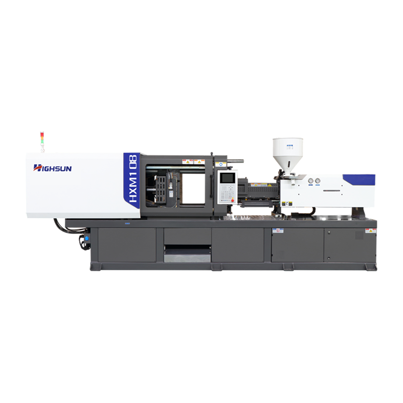
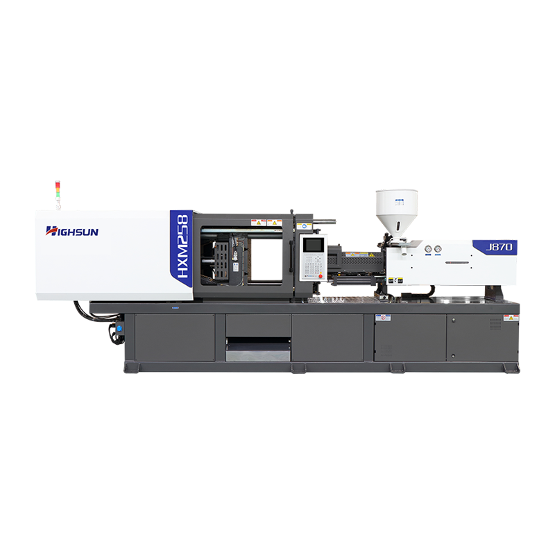 HXM258-I: HXM servo injection molding machineIn the expansive realm of injection molding equipment, the 258T Energy-Saving Servo Injection Molding Machine stands out as the ideal choice for small-scale production...View Product →
Machine data belongs in the design review, not in the commissioning week. A general-purpose servo machine in the 250-ton class, for example, sets a known tie bar spacing, platen pattern and shot capacity that the mold base must respect.
Large Molds Need a Different Set of Habits
Once parts pass roughly a kilogram, plate deflection and hot runner balance become the dominant risks. Support pillars must sit directly under the core, because an unsupported core plate bends and produces thickness variation across the part. Manifold balancing should keep fill differences between drops within a few percent, and two-platen machines often make sense because they shorten the machine footprint and reduce dry cycle time.
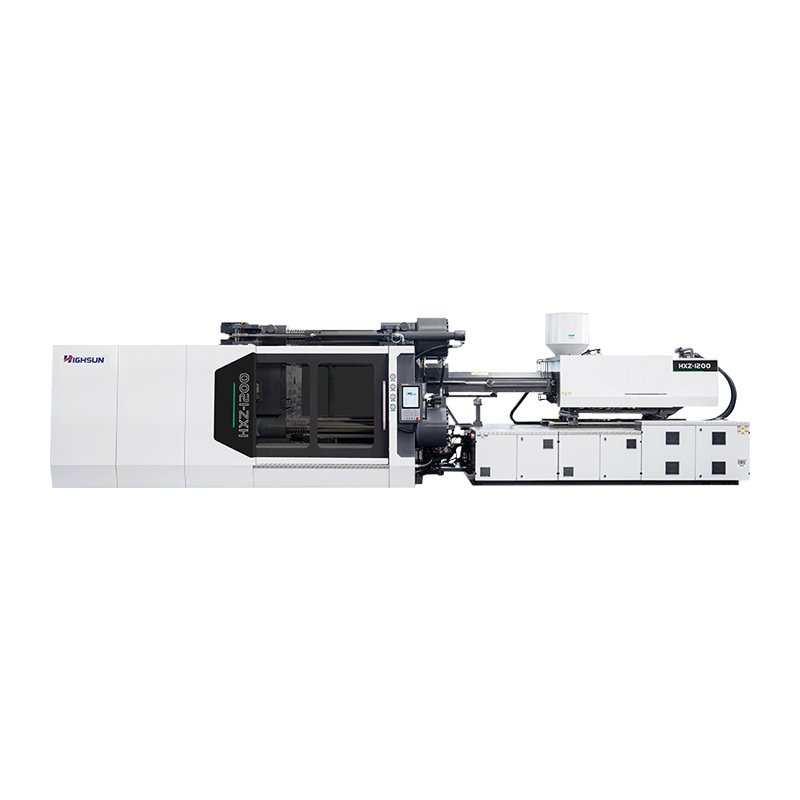 HXZ1200: two plate injection molding machinery seriesFour tie bars bear the same force evenly, so its parallelism of mold plate is good. Driven by two rapid oil cylinders, the mould movements are high speed, precise and ...View Product →
Structural and automotive parts are the typical home for this class of tool, where glass-filled resins add abrasion on top of the mechanical loads.
Defects That Trace Back to Mold Design
Most production problems blamed on the machine are decided much earlier. The table below maps the usual suspects to their design causes.
| Defect | Typical design cause | Design fix |
|---|---|---|
| Flash | Insufficient venting or weak plate support | Add or deepen vents; thicken the support plate |
| Short shot | Undersized gate or unbalanced runner | Enlarge the gate; rebalance runner diameters |
| Sink marks | Rib or boss thicker than the nominal wall | Hold ribs at 50 to 60 percent of wall thickness |
| Warpage | Uneven cooling between core and cavity | Balance circuits; add baffles in deep cores |
| Weld lines | Gate position splits the flow front | Move the gate; vent the weld line location |
| Ejector marks | Pins too small or too few | Increase pin diameter; add pins on stiff areas |
Frequently Asked Questions About Designing Injection Molds
Q1. What matters most when designing injection molds?
Part geometry and wall thickness come first, because they set cooling time and defect risk. Gate position, cooling balance and steel selection then follow from the part.
Q2. How many cavities should an injection mold have?
Balance output against machine shot capacity and tooling risk. Shot size should fall within roughly 20 to 80 percent of barrel capacity, and new parts are often launched on one or two cavities before scaling up.
Q3. What draft angle do injection molded parts need?
Plan on 0.5 to 1 degree for smooth walls, and add roughly 1 degree for every 0.025 mm of texture depth. Deep cores and flexible resins usually need more.
Q4. How does mold design affect injection molding cycle time?
Cooling is typically half to two-thirds of the cycle, so wall thickness and cooling layout dominate. Gate and runner sizing mainly influence packing time and scrap rate.
Q5. Which mold steel is best for high-volume production?
Hardened H13-type inserts at 48 to 52 HRC suit long runs and abrasive resins, while stainless S136-type steel at about 50 to 54 HRC handles corrosive or optical work. Pre-hardened P20 is adequate for lower volumes.
Q6. Can one mold design run on different injection molding machine brands?
Yes, if locating ring, sprue radius, ejector pattern, mold height and tie bar spacing are standardized. Those five interfaces decide whether a tool is portable between presses.
The test of a mold design is not how neat it looks in CAD, but whether it runs the same in hour one and hour ten thousand. Review the part geometry, the steel, the flow path, the cooling balance and the press interface while everything is still a drawing, and the tool will spend its life making parts instead of making excuses.
 +86-188 6861 6288
 haixiong@highsun-machinery.com
 No.36 Yongjiang South Road, Beilun District. Ningbo City, 315800, China