 ENG
 English
 русский
 Español
 Português
 عربى



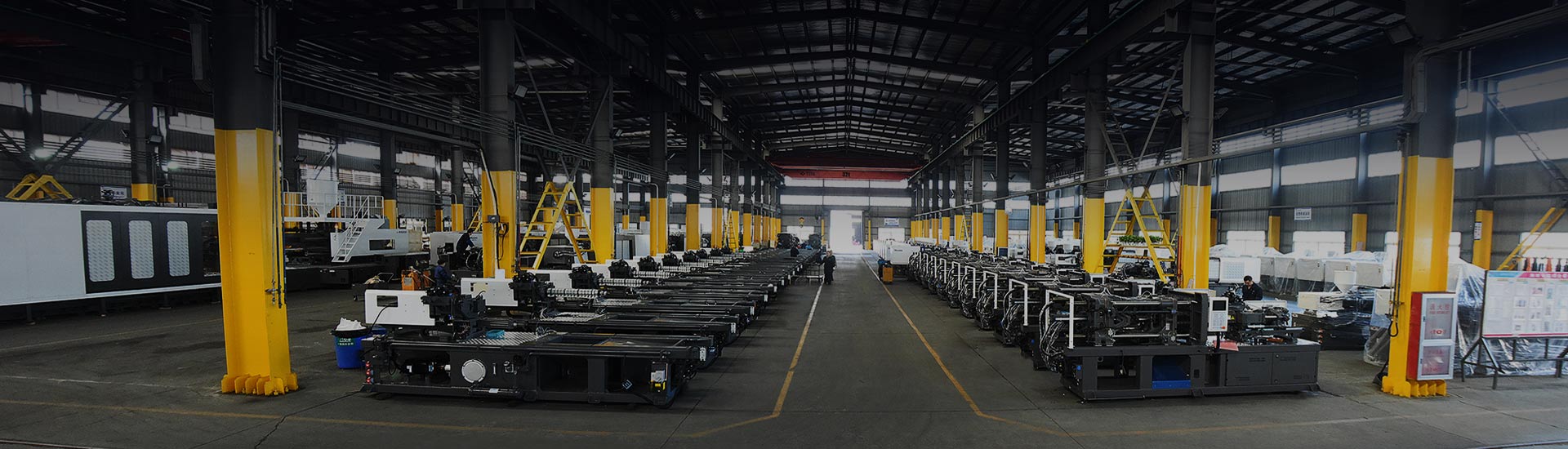
The injection moulding process is usually described as complicated. It is not; it is unforgiving. Four variables decide whether a cavity fills cleanly — melt temperature, injection speed, hold pressure and cooling time — and the machine's only real job is to repeat them identically, shot after shot, shift after shift. Screw geometry, servo response and control resolution all exist to make that repetition possible.
A 300-tonne press running a 2.5 mm polypropylene housing will spend roughly half of every cycle doing nothing but waiting for the part to solidify. That single fact drives most of what follows: how the process window is set, which machine type suits which part, and why two suppliers quoting the same tonnage can deliver very different unit costs.
Content
- 1 The Injection Moulding Process in Six Steps
- 2 Inside the Machine: Four Systems That Repeat the Cycle
- 3 Process Parameters: Where the Window Is Won or Lost
- 4 Matching the Machine Type to the Part
- 5 Defects Are Signals, Not Bad Luck
- 6 Cycle Time, Energy and the Real Unit Cost
- 7 Frequently Asked Questions
- 7.1 Q1. How long does a typical injection moulding process cycle take?
- 7.2 Q2. How do I calculate the clamp force I need?
- 7.3 Q3. Why do parts warp after ejection?
- 7.4 Q4. How much energy does an injection moulding machine use per kilogram?
- 7.5 Q5. What is the difference between servo and fixed-pump machines?
- 7.6 Q6. Which machine suits thin-wall packaging?
The Injection Moulding Process in Six Steps
The cycle is a fixed mechanical sequence, and every stage has a measurable duration. Clamping builds tonnage until the mould halves are locked. The injection unit then pushes melt into the cavity at a controlled speed, and holding pressure takes over at switchover, staying on until the gate freezes. Cooling follows — the stage most people underestimate — and for a 2–3 mm wall part it typically consumes 40–60% of the whole cycle, a range repeated across general moulding handbooks. The platens then open and the ejector system pushes the part clear before the sequence restarts.
| Stage | What the machine does | Indicative share of cycle |
|---|---|---|
| 1. Clamping | Platens close, clamp force builds, mould locks | 5–10% |
| 2. Injection (filling) | Screw advances, melt fills the cavity | 5–15% |
| 3. Holding (dwell) | Pressure held while the gate freezes and shrinkage is compensated | 15–25% |
| 4. Cooling | Part solidifies; screw recovery runs in parallel | 40–60% |
| 5. Mould opening | Clamp releases, moving platen retracts | 3–5% |
| 6. Ejection | Ejector pins push the part out, cycle restarts | 5–10% |
Where the cycle time actually goes
Read that distribution as a budget. If cooling holds the majority share, the fastest payback usually comes from mould cooling layout and part design, not from a bigger pump. Buying tonnage to solve a cooling problem is one of the most common purchasing mistakes in the industry.
Inside the Machine: Four Systems That Repeat the Cycle
A machine is only as consistent as its weakest sub-system, and the sub-systems interact. A fast injection unit paired with a slow clamp gives no cycle benefit at all.
Injection unit
The screw melts, meters and injects. Screw diameter and length-to-diameter ratio set the shot size and the shear history of the melt; a screw oversized for the job extends residence time and can degrade heat-sensitive resins.
Clamping unit
Toggle, hydro-mechanical or two-platen mechanisms generate clamp force and hold the mould closed against cavity pressure. Platen rigidity and tie-bar spacing matter as much as tonnage once moulds become large or deep-cored.
Mould and tooling
Gate position, cooling channel layout, draft angles, ejection and venting are decided at the tooling stage. A well-designed mould on a mid-range machine will outrun a poor mould on a premium one.
Drive and control
Fixed pump, variable pump, servo-hydraulic, hybrid or all-electric: the drive determines how much energy is wasted between movements and how precisely pressure and speed can be profiled. The controller then logs the profile so it can be repeated.
Process Parameters: Where the Window Is Won or Lost
Most defects are set before the first production shot, because one parameter was changed to hide a different problem. Document the window, then change one variable at a time.
- Melt temperature: measured with a purge probe, not read from the barrel display. Too low gives short shots and weld lines; too high gives silver streaks, flashing and longer cooling.
- Injection speed profile: fast fill suits thin walls, staged fill suits parts with thick-to-thin transitions. A common starting point is 95% cavity fill at first stage, then a low-pressure second stage for protection.
- Hold pressure and gate freeze: typically 50–80% of injection pressure, held until part weight stops changing. This is the single most effective lever against sink marks and warpage.
- Cooling time and mould temperature: cooling time is usually set to roughly 20–30 seconds per millimetre of wall as a starting estimate, then trimmed by part inspection. Uneven mould temperature on the two halves produces differential shrinkage and warp.
- Back pressure and screw recovery: enough back pressure to give a dense, consistent shot, not so much that melt temperature climbs during recovery and extends the next cooling phase.
Matching the Machine Type to the Part
Machine selection should follow the part, not the other way around. The useful questions are: how thick is the wall, how many cavities, how tight is the tolerance, and how many hours per year will the tool run? Four configurations cover most of that ground.
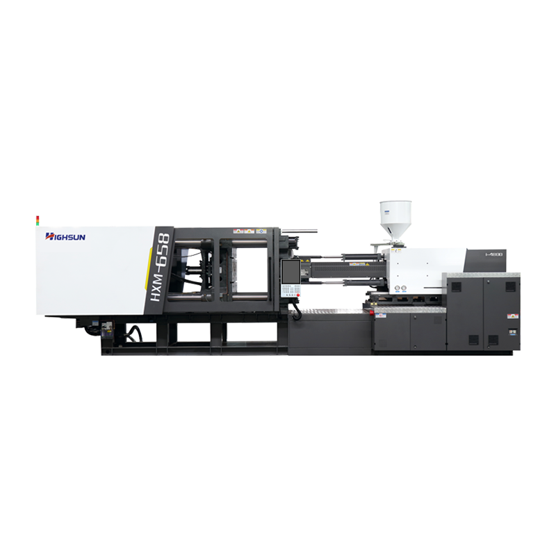
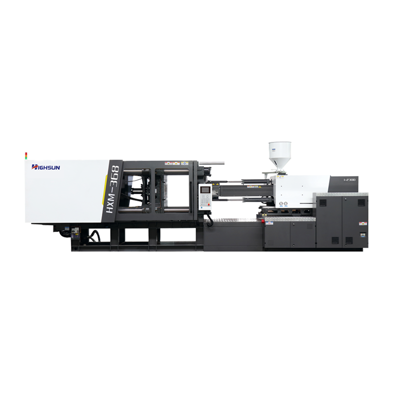
Servo-hydraulic machines are the general-purpose workhorse. The pump only delivers what each movement demands, so energy use tracks the actual cycle rather than the nameplate. For crates, buckets, housings and general industrial parts, a well-matched servo platform is usually the lowest total-cost starting point.
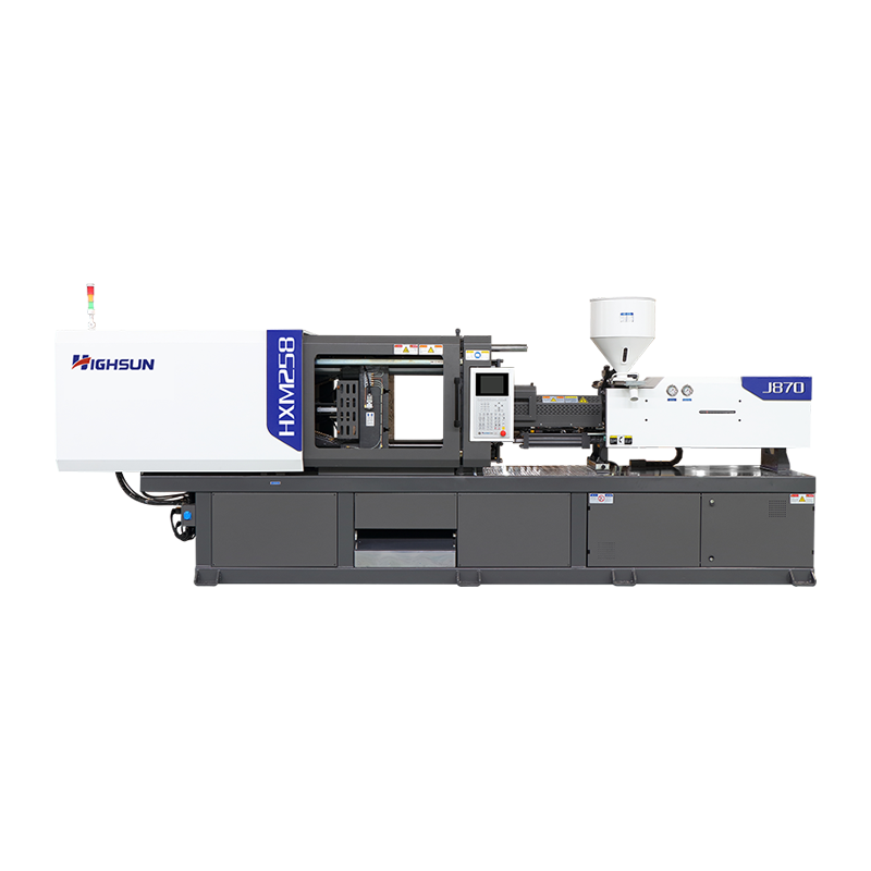 HXM258-I Energy-Saving Servo Injection Molding MachineA 258-tonne energy-saving servo machine for small-scale plastic production, offering a compact, flexible and cost-effective option for diverse SME molding needs.View Product →
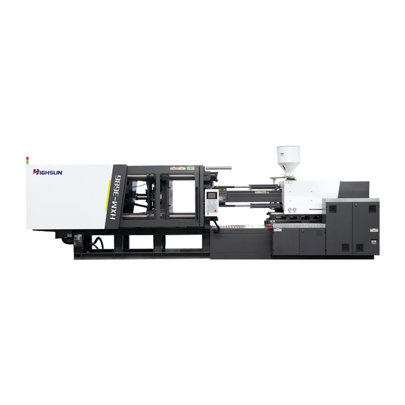
High-speed machines exist for a different reason: thin walls cannot wait. Filling has to finish before the melt front freezes, which means high injection rates, accumulator support and a clamp rigid enough to resist the resulting force. This is why thin-wall packaging is a machine-class decision, not a parameter tweak. HIGHSUN builds this configuration as the HXH series, with models from 280 to 450 tonnes.
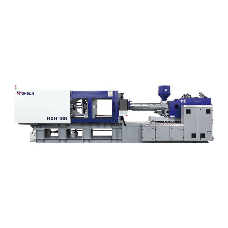 HXH388 High-Speed Thin-Wall Injection Molding MachineA 388-tonne high-speed machine for thin-walled parts, combining rapid plasticizing, precise injection and automated removal to shorten cycles in large-scale production.View Product →
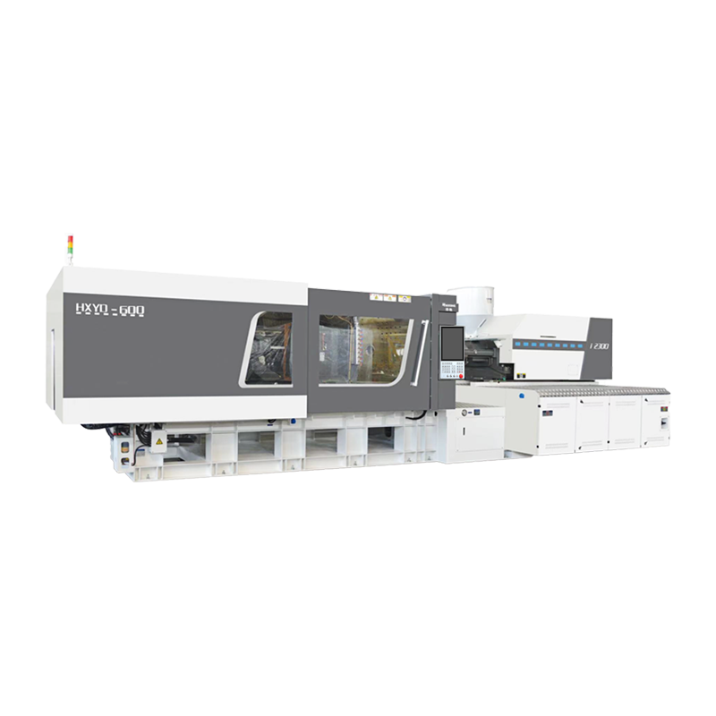
Large, deep parts push platen size and mould weight rather than shot size. A two-platen design removes the rear toggle, shortens the machine and makes mould changes faster on heavy tooling; the HXZ series spans 800 to 3,300 tonnes and is the usual choice once moulds exceed what a toggle machine handles comfortably.
 HXZ1400 Two-Platen Injection Molding MachineA 1,400-tonne two-platen machine for large, high-precision parts such as automotive components and appliance casings, with long mold-opening stroke and lower energy consumption.View Product →
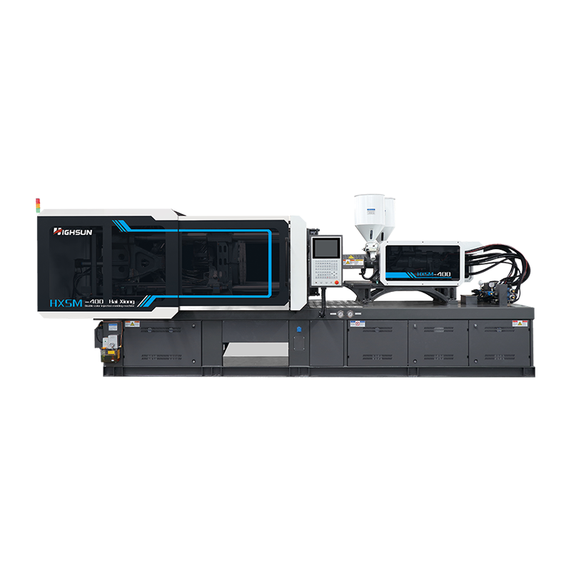
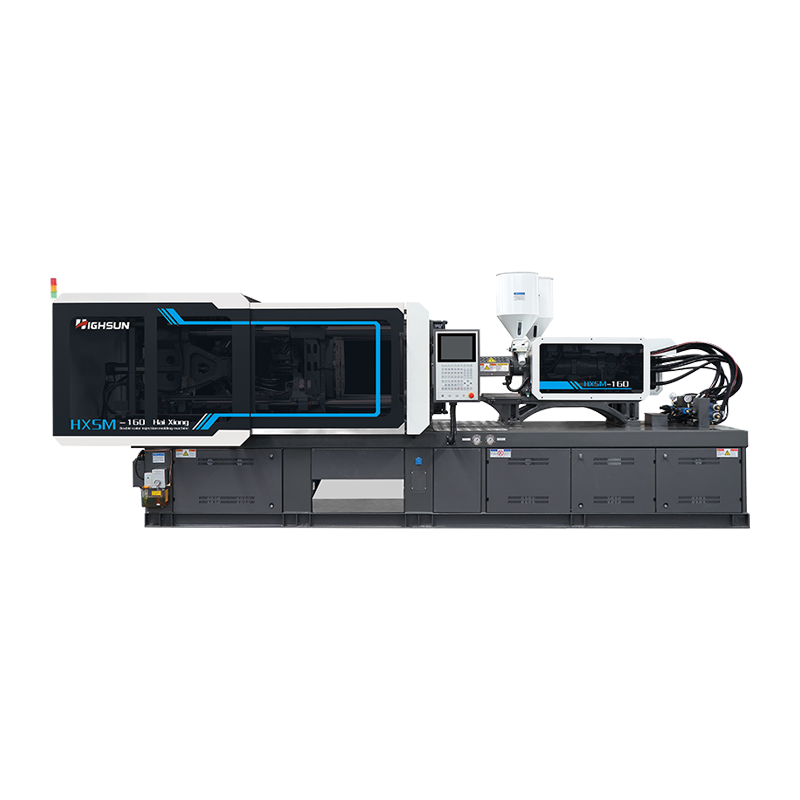
For PET preforms, PVC fittings or two-colour components, the barrel, screw, check valve and temperature strategy are all application-specific. Running PVC on a general-purpose screw, for example, invites dead spots and material decomposition during a stop.
Defects Are Signals, Not Bad Luck
Every common defect points at a specific stage of the cycle. Chasing it with the wrong parameter is what turns a two-hour setup into a two-week trial.
| Defect | Most likely cause | First thing to check |
|---|---|---|
| Short shot | Insufficient fill pressure or speed, cold melt | Shot size, injection speed profile, melt temperature |
| Sink marks | Under-packing at thick sections | Hold pressure and gate freeze time |
| Flash | Clamp force too low for cavity pressure | Tonnage against projected area, parting-line condition |
| Warpage | Differential shrinkage across the part | Mould temperature on both halves, cooling balance |
| Weld lines | Melt fronts meeting below fusion temperature | Injection speed, melt temperature, gate position |
| Silver streaks | Moisture or thermal degradation | Drying, residence time, barrel profile |
| Drag marks | Insufficient draft or polished-surface damage | Draft angle, ejection speed, mould finish |
Keep a process log for every tool: shot size, switchover position, hold pressure, cooling time and the resulting part weight. Weight is the cheapest in-line quality indicator you have, and a drifting part weight will predict a defect before the eye does.
Cycle Time, Energy and the Real Unit Cost
Unit cost is not machine price divided by output. It is cycle time, scrap rate, energy per kilogram and downtime added together. A machine that is 5% slower but holds tolerance for a full shift usually wins that calculation.
Energy is the easiest of these to measure and the hardest to guess. Servo and all-electric drives consume power on demand, so the saving is largest on long, cooling-dominated cycles where a fixed pump would otherwise circulate oil for nothing. Measure with a meter over a real shift rather than relying on catalogue values.
Large parts change the arithmetic again. Bigger automotive parts and appliance housings carry long cooling phases and expensive tooling, so short machine downtime and fast mould change matter more than a marginal injection-speed gain. On that scale, platen utilisation and preventive maintenance schedule become cost items in their own right.
Finally, keep the process documented and transferable. The injection moulding process that only exists in one operator's memory is a production risk, not a competitive advantage.
Frequently Asked Questions
Q1. How long does a typical injection moulding process cycle take?
Most 2–4 mm wall parts run between 15 and 45 seconds. Cooling dominates, so doubling wall thickness can add more time than any machine upgrade saves. Confirm the figure from your own tool trial rather than a catalogue value.
Q2. How do I calculate the clamp force I need?
Multiply the projected cavity area in cm² by cavity pressure — commonly 300–600 kg/cm² for commodity resins — then divide by 1,000 for tonnage. Add 10–20% margin for flow imbalance, then check the mould physically fits the platen.
Q3. Why do parts warp after ejection?
Warpage is differential shrinkage. Uneven mould temperature between the two halves, unbalanced packing or premature gate freeze are the usual causes. Check cooling and hold pressure before touching the injection speed.
Q4. How much energy does an injection moulding machine use per kilogram?
It depends on resin, wall thickness and drive type. Servo-hydraulic and all-electric machines draw power only when a movement demands it, so energy per kilogram should be metered over a full production shift, never read from a nameplate.
Q5. What is the difference between servo and fixed-pump machines?
A fixed pump runs continuously and discharges surplus flow through a relief valve. A servo drive matches pump output to the requested movement, which shows up clearly on the electricity bill during long cooling phases.
Q6. Which machine suits thin-wall packaging?
High-speed machines with accumulator-assisted injection, stiff clamping and fast screw recovery. Thin walls need filling speed and pressure response far more than they need extra tonnage.
 +86-188 6861 6288
 haixiong@highsun-machinery.com
 No.36 Yongjiang South Road, Beilun District. Ningbo City, 315800, China
