 ENG
 English
 русский
 Español
 Português
 عربى



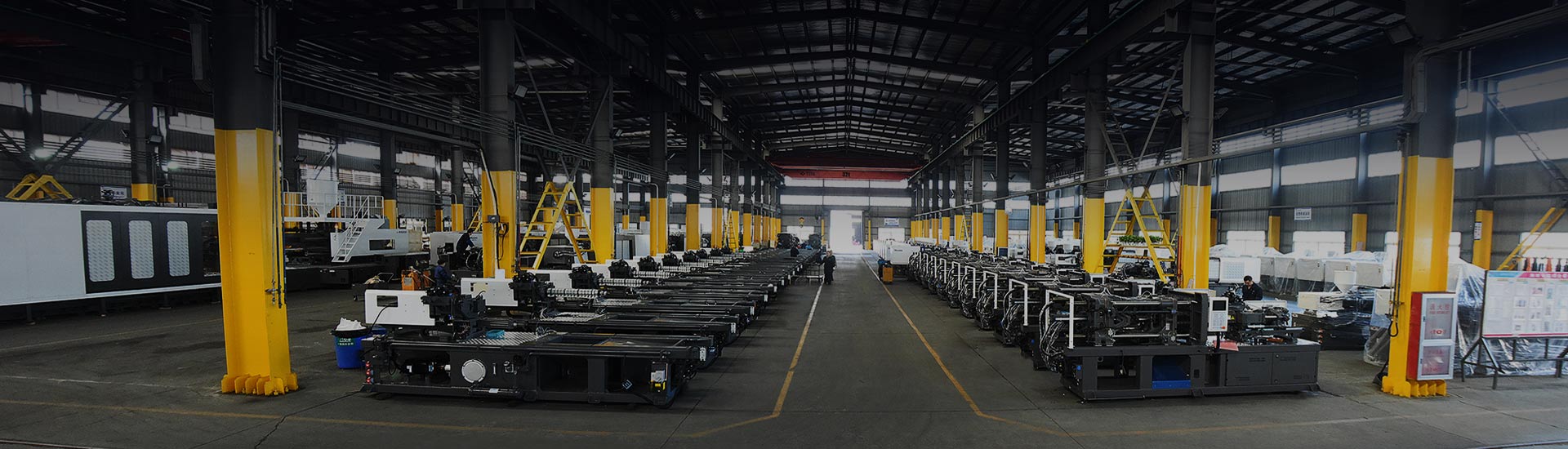
In a typical 25 to 35 second injection molding cycle, cooling eats up more than half the clock, while filling usually accounts for around 5 percent. Yet the parts that get scrapped on the floor are rarely scrapped because cooling was too short. Short shots, sink marks, flash and warpage trace back to filling and packing almost every time.
So here is the short version before the detail. The switchover from filling to packing has to be set by position, not by timer. Packing and holding are not the same job, and once the gate freezes, extra packing pressure buys you nothing. And cooling time scales roughly with the square of wall thickness, which means changing the part beats changing the parameters.
The rest of this article walks through the four stages in order, marks the numbers worth writing on the setup sheet, and points out where machine capability actually decides whether your process window is wide or narrow.
Content
- 1 Where the cycle time actually goes
- 2 Filling: the path matters more than the speed
- 3 Packing and holding: two words for two different jobs
- 4 Cooling: the largest block, with the least room to maneuver
- 5 Where the machine itself decides the outcome
- 6 What to write on the setup sheet
- 7 Frequently asked questions
Where the cycle time actually goes
Start with the time budget. The proportions below reflect the common structure of a general-purpose servo injection molding cycle. Real numbers shift with wall thickness, mold cooling design and material, but the broad shape rarely changes.
The useful reading is this. Cooling occupies the majority of the cycle but offers a narrow range of adjustment once the mold and material are fixed. Filling is a sliver of the clock yet it fixes where weld lines land, whether the part shorts, and how much internal stress you bake in. Packing and holding sit in between, take little time, and are the easiest settings to get wrong.
Filling: the path matters more than the speed
Filling is straightforward in principle. The screw moves forward and pushes melt into the tool. The parameter that actually governs quality is not the injection speed setting on the screen, it is the melt front velocity, the speed at which the flow front advances through the cavity.
The same injection speed profile produces very high shear rates in narrow runners and slows down noticeably in thick sections. The thinner the part, the more pronounced that spread becomes. In thin-wall work, filling is essentially a go or no-go stage, and a small drop in melt front velocity is the difference between a complete part and a short shot. The requirements for that kind of work are set out on the thin-wall product application page.
The practical setup order follows from this. Fix melt front velocity first, then check whether the flow front reaches all extremities at the same time, and only then trim the individual injection speed segments.
The end of filling needs to be pinned down just as carefully. The common industrial practice is to place the velocity-to-pressure switchover at 95 to 98 percent cavity fill, triggered by position rather than by time. Switch too early and the last regions to fill never get topped up, so sink marks appear far from the gate. Switch too late and the screw keeps pushing against an already full cavity, which raises the clamping load and produces flash.
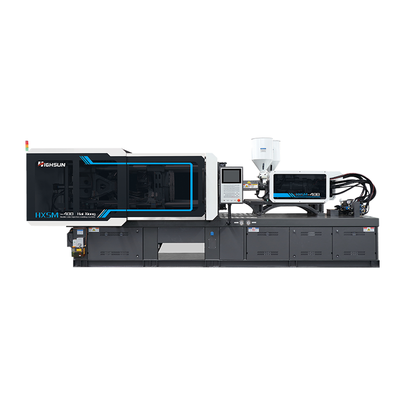
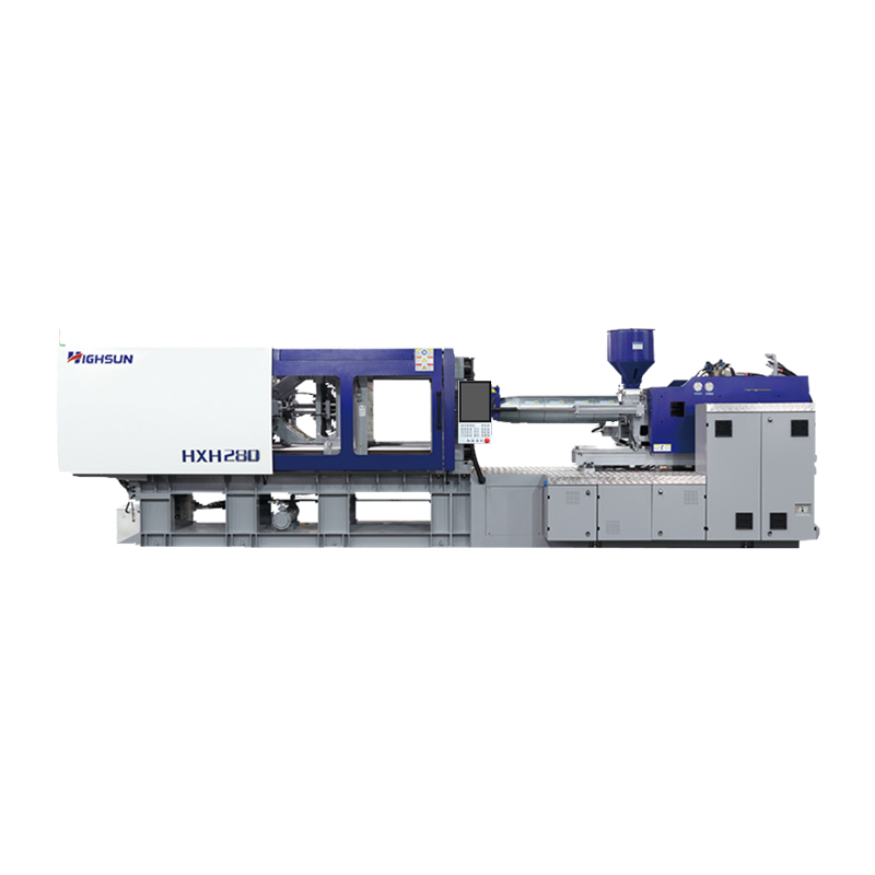
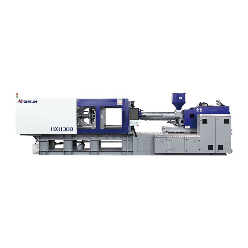 HXH388 388-Ton High-Speed Injection Molding Machine for Thin-Wall PartsA 388-ton HXH high-speed machine with 480 mm/s injection velocity, suited to thin-walled parts and demanding flow-length-to-thickness where standard hydraulic units may fall short.View Product →
On thin, long-flow parts the filling window narrows sharply. That is why a high-speed machine is not simply a nicer option in those jobs but a requirement. A standard hydraulic unit cannot accelerate the injection unit fast enough, and the melt front velocity never settles where you set it. The same logic applies to parts with demanding flow-length-to-thickness ratios.
Packing and holding: two words for two different jobs
In plenty of texts, packing and holding are treated as one stage. Inside the pressure phase they describe two distinct tasks, and confusing them is what produces over-long hold times and mysterious part defects.
Packing happens while the gate is still open. The screw continues forward and pushes additional melt into the cavity to offset the volumetric shrinkage that occurs as plastic cools. This action has a hard deadline, because once the gate seals, no more material can enter.
Holding is what happens after the gate freezes. Pressure is maintained, not to add material but to keep the part dimensionally locked while it continues to cool, so it cannot spring back or deform during ejection. The two share a pressure setting but serve completely different purposes.
The most common error on the shop floor is setting the packing time far beyond the gate freeze time on the assumption that a little extra pressure is a safety margin. That extra time adds nothing, burns energy, raises internal stress, and can crack parts during ejection.
The cavity pressure trace makes the sequence visible. Pressure climbs steeply during filling, peaks near the switchover point, holds roughly flat while the gate stays open, then begins to fall away once the gate seals and continues decaying through cooling until the mold opens.
How do you find the gate freeze time? The weight method is the most dependable. Run a series of parts with increasing packing times, weigh each one, and identify the point where part weight stops increasing. That is gate freeze. Setting packing time in the neighbourhood of that value is enough. Anything longer is just waiting.
Cooling: the largest block, with the least room to maneuver
Cooling runs from the end of packing until the part is stiff enough to eject. It usually accounts for 55 to 65 percent of the cycle, which is why every effort to shorten cycle time eventually lands here.
But cooling obeys a physical relationship that cannot be negotiated. The widely used cooling time estimation formula makes time proportional to the square of wall thickness. Double the wall and cooling takes roughly four times as long. Once the mold and material are fixed, that leaves a fairly short list of things you can actually change.
The variables that remain worth adjusting are these:
- Cooling circuit design and flow rate. Water needs to stay turbulent inside the channels, because heat transfer drops sharply once the flow turns laminar.
- Coolant temperature difference between inlet and outlet. A large spread usually means insufficient flow or a partly blocked line.
- Mold temperature uniformity. A locally hot patch produces sink marks and warpage before the overall mold temperature becomes a problem.
- Ejection temperature. Ejecting too early deforms the part after it leaves the mold; waiting too long costs cycle time for nothing.
Plastication overlaps with cooling. The screw recovers material while the part cools, so screw recovery normally does not add to the cycle, unless the screw runs so slowly that recovery outlasts cooling and becomes the new bottleneck.
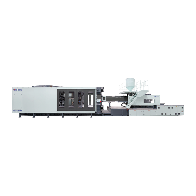
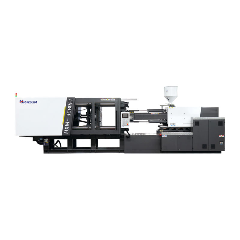 HXM368-PET 368-Ton PET Preform Injection Molding MachineA 368-ton hybrid PET-preform machine with 85 mm screw and 2632 g PET shot size, relevant where cooling and uneven wall sections affect preforms.View Product →
On a product like a PET preform, where the wall is thin but the base is thick, cooling control becomes unusually sensitive. Uneven wall sections reach their set state at different times, and simply extending cooling does not remove the warp. The fix lies in cavity temperature distribution working together with the packing profile.
Where the machine itself decides the outcome
Looking at all four stages together, machine capability helps in two places more than anywhere else: response speed during filling, and closed-loop pressure accuracy during packing and holding.
Filling demands that the injection unit reach its set velocity within a very short stroke and hold it as the flow front advances. A slow hydraulic response produces a wandering melt front, and thin-wall parts suffer first. Servo drive makes a visible difference here, not so much in energy consumption as in whether the commanded velocity profile is actually delivered.
Packing demands a clean transition into pressure and a stable closed loop afterwards. If pressure control oscillates, cavity pressure oscillates with it and part weight consistency degrades.
This is not a ranking so much as a picture of trade-offs. All-electric machines lead on precision and energy use but carry higher purchase and maintenance costs. Servo hydraulic sits at the balance point for most general work. Fixed-pump machines still make sense where the budget is tight and the demands on speed and accuracy are modest.
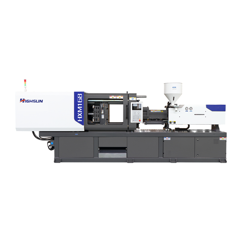
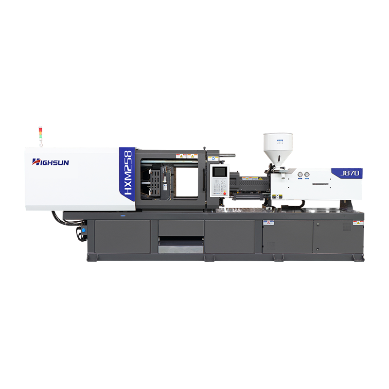 HXM258-I 258-Ton Servo Injection Molding Machine for Small-Scale ProductionA 258-ton servo hydraulic machine positioned for small-scale production; its balance of efficiency and cost suits general work where stable packing and dimensional consistency matter.View Product →
For products such as automotive components, where dimensional consistency is closely watched, stable pressure during packing usually matters more than raw filling speed. That pattern shows up clearly in automotive part applications, where dimensional drift between shots is the main rejection cause.
What to write on the setup sheet
Each stage contributes one or two numbers that belong on the sheet. The table below gathers the ones that carry the most weight.
| Stage | Parameter to record | Direction or range | Why it matters |
|---|---|---|---|
| Filling | Melt front velocity | Set by material and wall thickness | Governs shear rate, weld line position, and whether the part fills at all |
| Filling | V/P switchover position | 95 to 98 percent cavity fill | Prevents short shots at one extreme and flash at the other |
| Packing | Packing pressure | Roughly 50 to 80 percent of peak injection pressure | Offsets shrinkage while the gate is still open |
| Packing | Packing time | Confirmed by the part-weight method | Anything beyond gate freeze adds stress rather than material |
| Cooling | Coolant inlet and outlet temperature | A small, steady difference across the circuit | A widening gap points to blocked or undersized channels |
| Cooling | Ejection temperature | Below the point where the part holds its shape | Ejecting too warm causes warpage and ejection marks |
Treat the ranges as orientation only. For any specific product, three trials will settle the process: one to find the filling endpoint, one to find gate freeze by weight, and one to confirm ejection temperature. With those three data points, the parameters for all four stages fall into place.
Frequently asked questions
Q1. Which injection molding stage takes the longest?
Cooling, in most cases. It typically accounts for 55 to 65 percent of the cycle, so any serious attempt at cycle time reduction starts there.
Q2. What is the difference between packing and holding?
Packing adds material while the gate is open. Holding maintains pressure after the gate freezes, so the part cannot spring back during cooling.
Q3. Why do sink marks appear even with long packing time?
Once the gate freezes, extra packing pressure cannot push more melt in. Sink marks then usually point to insufficient holding pressure or uneven cooling.
Q4. How can cooling time be shortened in injection molding?
Keep coolant flow turbulent, balance mold temperature, and reduce wall thickness where the design allows. Wall thickness has the largest single effect.
Q5. Where should the V/P switchover point be set?
By position, at 95 to 98 percent cavity fill. Time-based switchover drifts with material viscosity and produces inconsistent parts.
Q6. Does cooling time affect warpage of molded parts?
Yes. Uneven cooling creates differential shrinkage across the part. Extending cooling alone rarely fixes it; cavity temperature balance usually does.
 +86-188 6861 6288
 haixiong@highsun-machinery.com
 No.36 Yongjiang South Road, Beilun District. Ningbo City, 315800, China
