 ENG
 English
 русский
 Español
 Português
 عربى



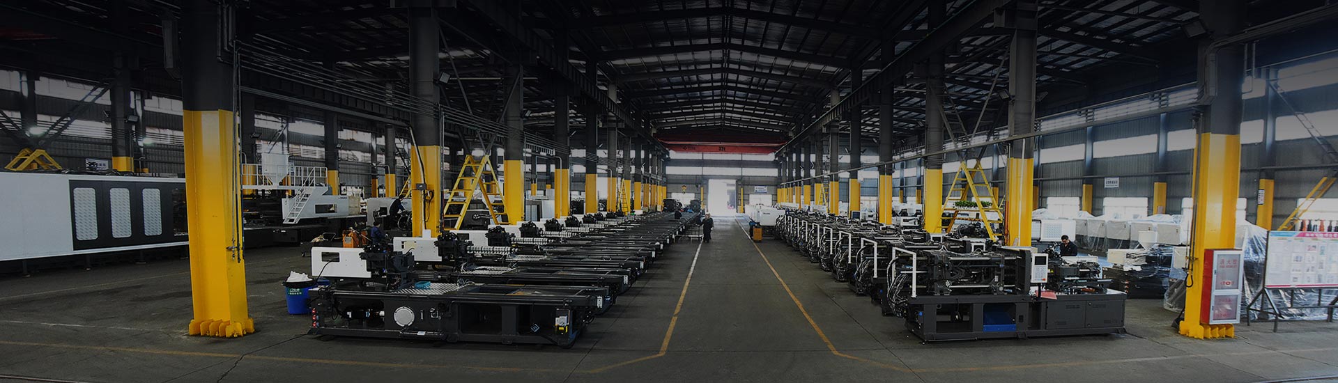
An appliance molder orders a 650-tonne press and a two-cavity housing tool in the same week. The machine lands first. The mold arrives three weeks later, and the first mounting attempt fails by 18 mm: the closed height of the tool is below the machine's minimum mold height, so the toggle never builds full clamping force. The fix is a spacer plate, not a new machine, but the line still loses two weeks of planned output.
That is what happens when an injection molding machine mold is treated as an accessory bought after the press. It is not. The tool is a machine specification, and four numbers decide whether it can run at all: closed mold height, mold width against the tie-bar spacing, projected area against rated clamping force, and the locating ring and nozzle interface. Everything else - ejector stroke, water-line clearance, core-pull sequencing, crane access - decides how fast and how reliably you run, not whether you run.
Content
- 1 Match the tool drawing to the datasheet, line by line
- 2 Clamping force: start from the mold, not from the quote
- 3 Mold height, daylight and when a two-platen machine wins
- 4 Nozzle, locating ring and ejector: the three-millimetre problems
- 5 When cycle time is the specification, the mold changes class
- 6 What to send a machine builder before you order
- 7 Frequently asked questions
Match the tool drawing to the datasheet, line by line
The fastest way to catch a mismatch is to put the mold drawing next to the model datasheet and check six interfaces. Most suppliers publish these values per model, and most buyers check only the first one.
| Mold parameter | Matching machine value | Typical failure when mismatched |
|---|---|---|
| Closed mold height | Minimum and maximum mold height (daylight) | Toggle cannot lock, or the tool cannot be clamped at all |
| Mold width and base footprint | Tie-bar clear distance and platen size | Tool cannot be lowered between the bars; uneven platen loading |
| Projected area times cavity pressure | Rated clamping force | Flash, short shots, or over-clamping that damages the tool |
| Locating ring diameter | Platen locating bore (commonly 100, 125 or 160 mm) | Nozzle misalignment and sprue leakage |
| Sprue radius and orifice | Nozzle radius and nozzle bore | Melt leaks at the sprue bushing, stringing, cold slugs |
| Ejector pattern and stroke | Knockout hole pattern and ejector stroke | Parts stick, ejector pins bend, bosses crack |
Automotive work exposes the geometry problem fastest. A fascia mold with a long core-side stack can exceed 900 mm in closed height, which rules out most mid-size toggle machines no matter how much tonnage they carry. Molds for automotive interior and exterior parts are therefore specified against daylight and platen size first, tonnage second.
Clamping force: start from the mold, not from the quote
Clamping force is where most mismatches begin, because buyers compare tonnage on the quotation instead of projected area on the tool drawing. The working formula is simple: clamping force in tonnes = projected area in square centimetres multiplied by cavity pressure in bar, divided by 1000.
Take a two-cavity housing tool with 220 cm2 of projected area per cavity. Total projected area is 440 cm2. At 450 bar of cavity pressure that is 198 tonnes of holding force before any margin. Add 10 to 20 percent for safe running and the press needs roughly 220 to 240 tonnes - a mid-size machine, not the 400-tonne machine the shop floor usually asks for.
Cavity pressure is the number people guess. Published processing guidance commonly places it at 300 to 500 bar for commodity polyolefins, 500 to 700 bar for engineering resins such as ABS, PA and PC, and above 800 bar for thin-wall parts with long flow paths. Undersizing shows up immediately as flash on the parting line and short shots at the flow end. Oversizing is quieter but not free: excess clamp force deflects the platens, vents the tool unevenly and shortens mold life.
Indicative clamping force band by part family
Common mold and machine risks: a tool quoted with a 1.5 safety factor on a machine already running at 90 percent of rated force; a shallow mold on a large platen, where the clamp force is applied off the platen centre; a deep-core mold on a machine with insufficient opening stroke, so the part cannot be ejected without a robot reaching inside.
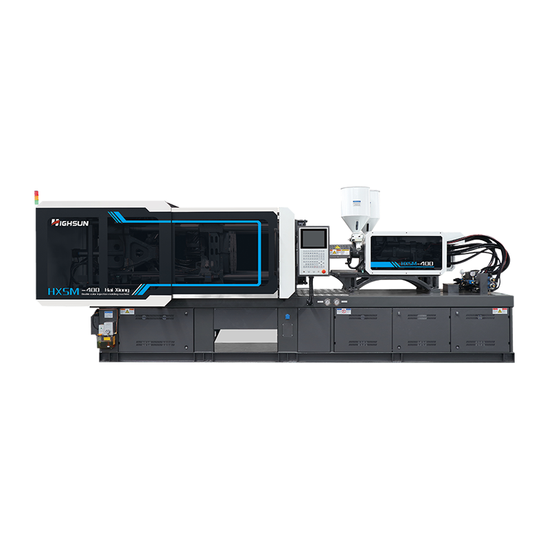
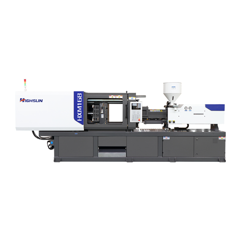
 HXM328 328-Tonne Servo Injection Molding MachineA 328-tonne servo toggle machine in the HXM series, with model-page platen, mold-height and ejector data for checking against tool drawings.View Product →
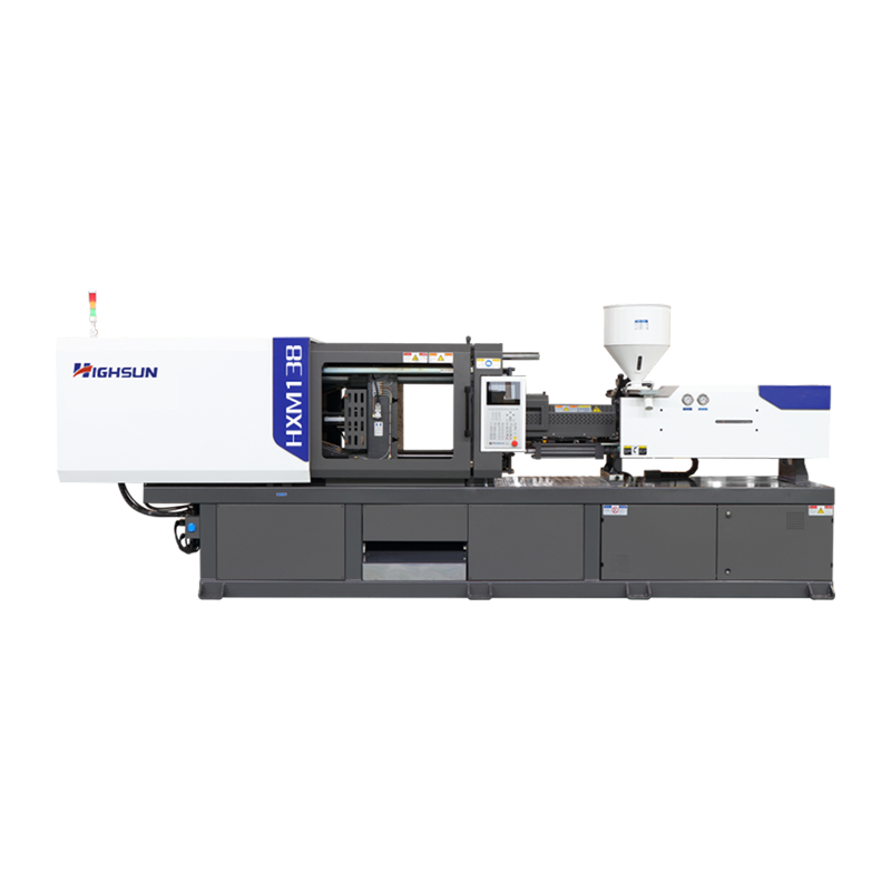
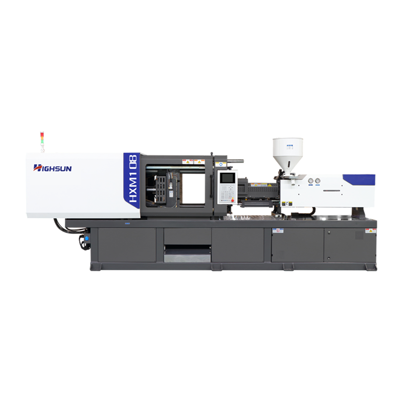
For the 200 to 400 tonne band, where most appliance housings, household goods and interior trim tools sit, a servo toggle machine is the usual starting point. HIGHSUN builds that class around the HXM series, and the individual model pages list platen, mold height and ejector data you can check directly against a tool drawing.
Mold height, daylight and when a two-platen machine wins
Closed mold height sets the physical envelope. The datasheet gives a minimum and a maximum; the distance between them is the adjustment stroke. A tool thinner than the minimum needs a spacer plate, which is cheap but changes the clamp stack. A tool taller than the maximum simply will not close, and no amount of tonnage fixes it.
Two-platen machines replace the toggle linkage with four short-stroke hydraulic cylinders. The practical result is a longer opening stroke and a shorter machine footprint for the same clamping force, which matters for deep-draw parts, stack molds and any tool with a long core. If a mold needs more than about 1.5 times its own height in opening stroke, that architecture is usually the cheaper answer.
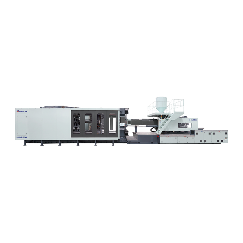
 HXZ1000 1000-Ton Two-Platen Injection Molding MachineA 1000-tonne two-platen model in the HXZ range, offering long opening stroke and compact footprint for large, deep or heavy molds.View Product →
The HXZ two-platen range covers 800 to 3300 tonnes and is aimed at exactly this case: large, deep or heavy tooling that needs long opening stroke and a platen that stays flat under load.
Nozzle, locating ring and ejector: the three-millimetre problems
The clamping side of the interface is forgiving to a few millimetres. The injection side is not. Three details generate most of the small, expensive failures on a new tool.
- Locating ring. The ring centres the mold on the platen and defines the nozzle position. Bore sizes follow common standards such as Euromap 2 and SPI practice, with 100, 125 and 160 mm covering most tooling. A ring that is 2 mm undersized lets the sprue bushing sit off-centre, and the nozzle then leaks under pressure.
- Nozzle radius and bore. The nozzle tip radius must match the sprue bushing radius, and the nozzle bore should be slightly smaller than the sprue orifice so that cold slugs stay in the runner, not in the tip. A mismatch shows up as a ring of frozen melt around the bushing after every cycle.
- Ejector stroke and pattern. Knockout hole spacing is rarely identical between builders. Adapter plates solve it, but the stroke itself must clear the part; a deep part that needs 120 mm of ejection on a machine rated at 100 mm will stick, and the operator will compensate by over-clamping.
Water and hydraulic line routing belongs in the same check. A tool with manifolds on the operator side can look fine on the drawing and still foul the tie bars once hoses are fitted. Cleaning and polishing access matters too - routine mold polishing and maintenance is far easier when the tool can be swung clear of the platens.
When cycle time is the specification, the mold changes class
Thin-wall packaging pushes both the tool and the machine into a different category: cavity pressures above 800 bar, fill times under half a second, and 8- to 32-cavity tools that must open, eject and close in under two seconds. Here the machine choice is driven by injection rate and clamp repeatability together, because a fast fill on an unstable clamp produces flash just as reliably as an undersized press.
Relative characteristics by clamping architecture
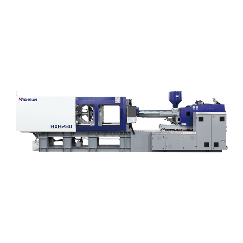
 HXH450 High-Speed Injection Molding MachineA high-speed HXH-series machine with a rigid clamp unit and expanded mold stroke, suited to thin-walled and complex plastic parts.View Product →
High-speed machines in the HXH range are built for that pattern: fast dry-cycle, a rigid clamp unit and an injection unit sized for thin sections rather than for screw recovery on thick walls.
What to send a machine builder before you order
None of this requires a special process. It requires a folder of tooling data sent at the quotation stage rather than the installation stage.
- Closed mold height, plus minimum and maximum opening stroke needed for part removal.
- Mold base width and depth, including any core-pull cylinders that protrude.
- Projected area per cavity, cavity count and the expected cavity pressure range.
- Locating ring diameter, sprue radius, sprue orifice and total shot weight.
- Ejector hole pattern, ejector plate stroke and required ejection force.
- Water circuit count, port positions and whether a manifold sits on the operator side.
- Maximum mold weight, plus the crane or hoist plan for the bay.
- Any special sequence - core pull, valve gate, hot runner zone count.
Send that and the machine specification stops being a catalogue choice and becomes an engineering match. The press that arrives will fit the mold that arrives, and the only variable left is process tuning.
Frequently asked questions
How much clamping force does my mold need?
Multiply the total projected area of all cavities in square centimetres by cavity pressure in bar, divide by 1000, then add 10 to 20 percent. A 440 cm2 tool at 450 bar needs about 200 tonnes of holding force, so roughly 230 tonnes on the machine.
What is mold height on an injection molding machine?
It is the closed thickness of the mold, measured from the fixed platen face to the moving platen face. Every machine has a minimum and maximum mold height; outside that window the toggle cannot build clamping force or the mold physically will not fit.
Can a mold be too small for a machine?
Yes. A thin tool on a large platen concentrates force in the middle of the platen, increases deflection and can bend the mold base. The usual remedies are a spacer plate and a properly sized support pad, not more tonnage.
What is tie-bar clear distance?
It is the free opening between the tie bars, measured horizontally and vertically. The mold base, core-pull cylinders and hose manifolds must all pass through that space when the tool is lowered in by crane.
Why does the nozzle leak at the sprue?
Usually a radius mismatch between the nozzle tip and the sprue bushing, a worn locating ring that has moved the tool off centre, or insufficient nozzle contact force. Check the ring bore before adjusting injection pressure.
What should I include in an injection molding machine quote request?
Send the mold drawing, closed height and stroke requirement, projected area and cavity pressure, sprue and locating ring dimensions, ejector pattern, water circuit layout and maximum tool weight. Builders can then confirm the model instead of estimating.
 +86-188 6861 6288
 haixiong@highsun-machinery.com
 No.36 Yongjiang South Road, Beilun District. Ningbo City, 315800, China
