News

What are the structural characteristics of the injection molding motor template?

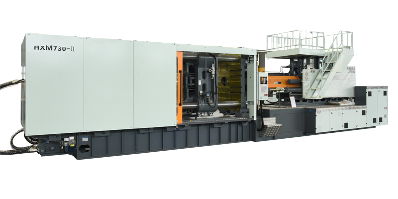
The template is usually fixed template and mobile template. The fixed template is divided into front template (or head plate) and rear template (tail plate). The function of the template is to form a rigid frame with 4 coring columns to form a mold-containing space. When locking the mold, the template has to withstand bending stress and compression deformation. Therefore, the template should have the following characteristics: 1) The template is made of cast steel or ball milled cast iron with good toughness and rigidity to ensure sufficient toughness, rigidity and wear resistance. 2) The design of the external structure and size of the template is to design the fixed template into a flat working surface with supporting rib structure in the cross section to overcome the bending stress that must be borne during work. The working plane of the template should be annealed, and the surface roughness of the mechanical processing of the template should not be greater than 1.25 μm. When machining, it should be divided into rough machining and finishing twice to reduce the deformation after machining and ensure the accuracy requirements of the mutual position of each part. 3) Assembling the template and the collar column is a sliding fit. The H7/f7 matching system is adopted, and the synchronization accuracy is relatively high. Therefore, the 4 assembly holes and working planes on the template are required to be processed and formed in one clamping on the boring machine to ensure to ensure the synchronization accuracy. The symmetrical accuracy requirements of the center lines of the 4 holes are required to ensure the non-parallel accuracy requirements of the working surface of the template and the moving template (the clamping surface of the upper mold). 4) The sliding foot structure is adopted between the movable template and the slide track. Between the slide foot and the track, an oil mold effect is formed by lubricating oil to produce an oil film and form a good sliding fit. The adjustment device of the movable template and the sliding foot can maketimely adjustments. Some models also add rail steel belts to prevent excessive wear between the racks. Common sliding feet have the following 4 forms. details as follows: ①The adjustment device is at the bottom of the movable template, and the gap between the rail slide and the sliding foot is adjusted through the upper adjustment screw; ②The adjusting device is also at the bottom of the movable template, and the gap between the slide plate and the sliding foot of the track is adjusted through the upper and lower adjusting screws; ③The adjusting device is on the side of the movable template, and the gap between the slide plate and the sliding foot of the track is adjusted by adjusting the screw; ④The adjusting device is under the movable template, and the gap is adjusted by adjusting the inclined iron of the sliding foot.  

WE'RE HERE TO HELP

Not sure where to start?

Our team of digital and business experts will guide you to the right direction.

Let's Talk
TOP