 ENG
ENG  English
 русский
 Español
 Português
 عربى
عربى


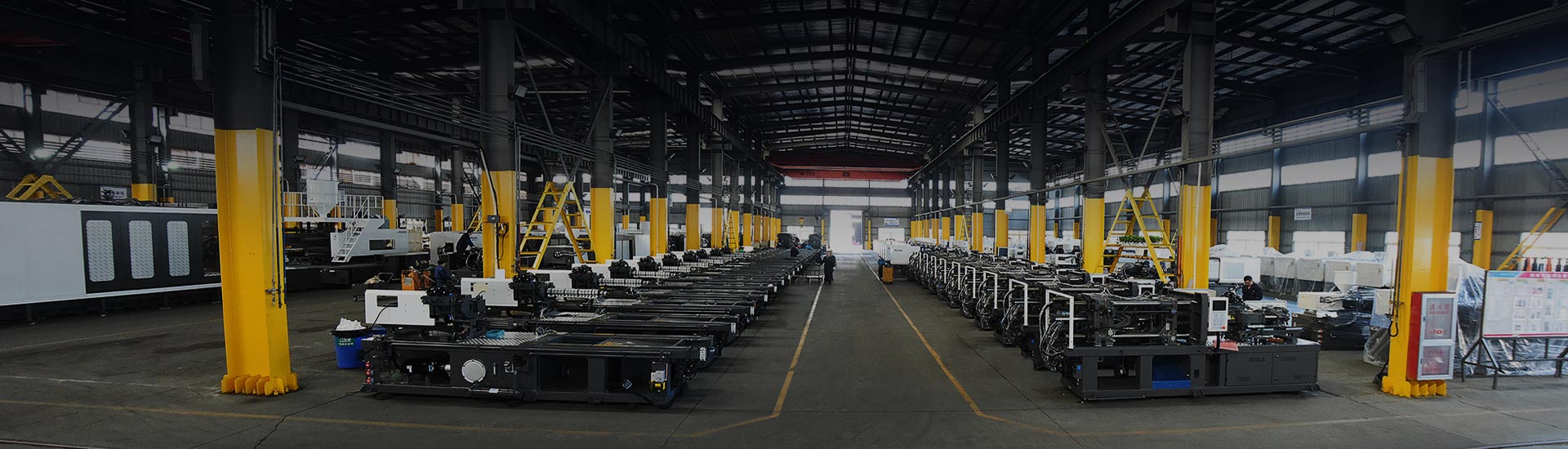
You are in the middle of a trial run with a brand-new mold. The first shot comes up short, the second flashes along the parting line, and the process engineer starts changing parameters without a clear diagnosis. The real issue is rarely a single setting; it is a breakdown somewhere in the injection moulding process stages. When each stage has a defined job, finding the weak link becomes much faster.
Content
- 1 The Injection Moulding Process Stages at a Glance
- 2 Stage 1: Clamping – Locking the Mold Against Injection Pressure
- 3 Stage 2: Injection – Filling the Mold With Molten Plastic
- 4 Stage 3: Holding Pressure – Compensating for Shrinkage
- 5 Stage 4: Cooling – The Longest Phase of the Cycle
- 6 Stage 5: Mold Opening and Ejection – Releasing the Part Safely
- 7 Post-Processing and Quality Inspection
- 8 Optimising the Whole Injection Moulding Cycle
- 9 Injection Moulding Process Stages FAQ
- 9.1 What are the main stages of the injection moulding process?
- 9.2 What is an injection moulding machine and how does it work?
- 9.3 How long does an injection moulding cycle take?
- 9.4 What causes common injection moulding defects?
- 9.5 How do I choose the right injection moulding machine?
- 9.6 How can I reduce injection moulding cycle time?
The Injection Moulding Process Stages at a Glance
Guides sometimes describe four or five steps, but the machine cycle itself follows six distinct stages that happen in a fixed order during every moulding cycle:
- Clamping – closing and locking the mold
- Injection – filling the cavity with molten plastic
- Holding pressure – compensating for shrinkage after fill
- Cooling – solidifying the part to a safe ejection temperature
- Mold opening – separating the mold halves
- Ejection – removing the finished part
The sequence applies to almost every thermoplastic moulding job. For a wider discussion of how the machine and mold work together, see our article on the basic process of an injection molding machine. The diagram below shows the main machine components that execute these stages.
Typical layout of an injection moulding machine: material is plasticised in the injection unit, then forced into the mold in the clamping unit while the control system coordinates the sequence.
Stage 1: Clamping – Locking the Mold Against Injection Pressure
Clamping does more than close the mold. The clamping unit must generate enough force to keep the mold shut while the melt pushes against the cavity walls. If the clamping force is too low, the mold opens slightly at the parting line and flash appears.
The required clamping force is calculated from the projected cavity area multiplied by the effective cavity pressure. A part with a projected area of about 200 cm² and an effective cavity pressure of 400 bar needs roughly 800 tonnes of clamping force. This is one of the first calculations you should make before selecting a machine.
Large molds and two-platen machine selection
For large parts such as automotive panels, pallets and logistics crates, a two-platen machine is often a better choice than a toggle machine because the space between the platens is longer and the footprint is shorter. The HXZ800 two-platen injection molding machine offers 800 tonnes of clamping force and is designed for molds with large dimensions. When evaluating this stage, also check tie-bar spacing, maximum mold height and dry-cycle speed, not just the clamping force figure.
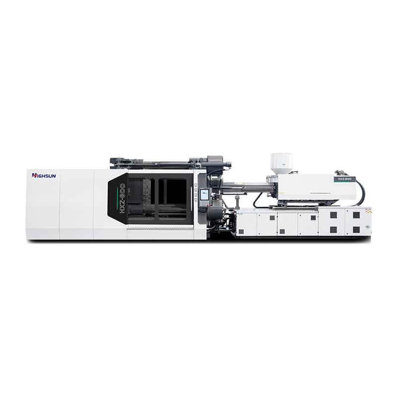 HXZ800: two plate injection molding machinery series Suppliers, OEM/ODM Company Ningbo beilun highsun machinery Co., ltd is top HXZ800: two plate injection molding machinery series suppliers and OEM/ODM company in Chi...View Product →
Stage 2: Injection – Filling the Mold With Molten Plastic
Before injection begins, the screw rotates to plasticise the material and moves back to accumulate a melt pool at the front of the barrel. When the screw stops rotating, it acts as a plunger and pushes the melt through the nozzle into the mold cavity.
Injection speed and pressure determine how the melt fills the cavity. A typical multi-stage injection profile starts at a low speed to avoid jetting at the gate, then accelerates to fill the main body of the cavity, then slows down again near the end to prevent over-packing. The transfer point from injection speed control to pressure control, called the V/P switch-over, has a direct effect on part weight consistency.
Why a servo-driven injection unit helps
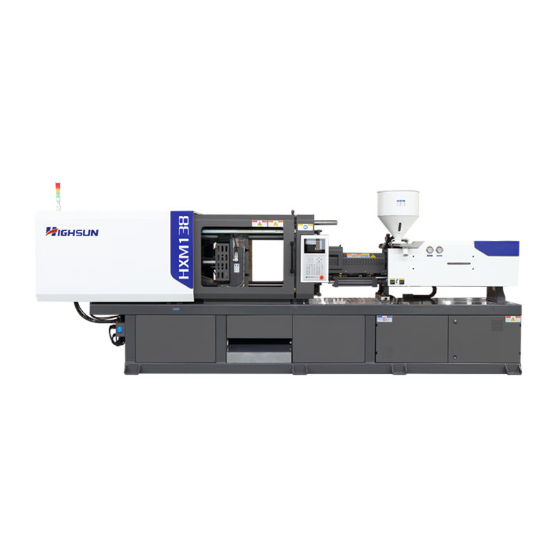
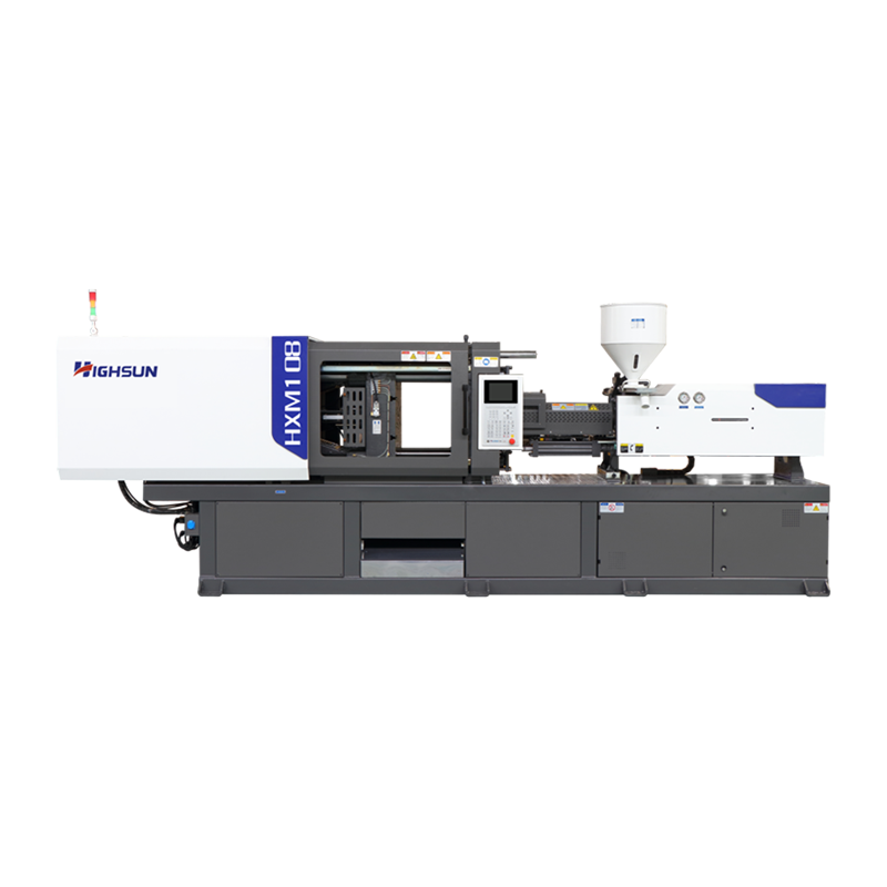
Servo-driven machines react to speed and pressure changes faster than fixed-pump hydraulic systems, which keeps the cavity pressure curve stable from shot to shot. The HXM208 servo injection molding machine uses a variable-output servo pump and closed-loop control to reproduce the injection profile with high repeatability. In multi-cavity molds this difference shows up directly in the dimensional spread of the parts.
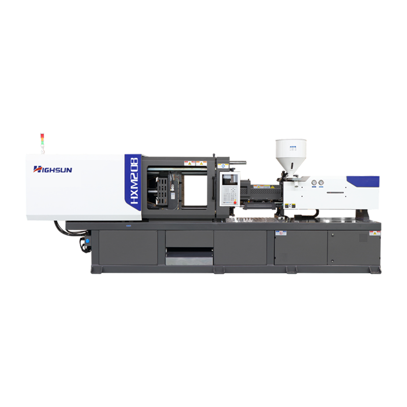 HXM208: HXM servo injection molding machine Suppliers, OEM/ODM Company - Ningbo Ningbo beilun highsun machinery Co., ltd is top HXM208: HXM servo injection molding machine suppliers and OEM/ODM company in China, The e...View Product →
Stage 3: Holding Pressure – Compensating for Shrinkage
Once the cavity is filled, the material starts to cool and shrink. Holding pressure keeps a small amount of additional melt flowing into the cavity until the gate freezes. This is the stage that controls sink marks and final part dimensions.
Too little holding pressure creates sink marks, high shrinkage and sometimes short shots at the far end of the mold. Too much holding pressure over-packs the cavity, which can cause warpage, residual stress and difficult ejection. For precision parts, the position where the screw stops and holding begins should be tuned with the help of cavity pressure data if the machine supports it.
Stage 4: Cooling – The Longest Phase of the Cycle
Cooling starts the moment the melt touches the cavity wall, but the machine usually counts the cooling phase from the end of holding to mold opening. During this phase, the part has to cool below the material's heat deflection temperature so that ejection does not deform it.
In a typical thin-wall moulding cycle, cooling accounts for roughly half of the cycle time, as shown in the chart below. The exact share depends on wall thickness and material; thick engineering parts can spend 70–80% of the cycle just cooling.
Typical time distribution for a thin-wall thermoplastic part. Actual values depend on material, wall thickness and mold cooling design.
Mold cooling design is therefore the biggest lever for reducing cycle time. Cooling channels should follow the cavity shape, and the water temperature should be uniform across both mold halves. A temperature difference of 10°C between the moving and fixed sides is often enough to produce warpage in an otherwise sound design.
Stage 5: Mold Opening and Ejection – Releasing the Part Safely
When the part is rigid enough, the mold opens and the ejector system pushes the part off the core. Ejection speed should be as high as the part geometry allows. Deep ribs, small draft angles and fragile features often force slower ejection, which adds to the cycle time.
If the part sticks, the problem is usually in the earlier stages: excessive shrinkage on the core, a low draft angle, or a holding pressure that over-packed the part. Ejector pin marks on the visible surface can usually be traced back to insufficient or uneven ejection area, so the ejector layout should be reviewed together with the mold design.
Post-Processing and Quality Inspection
After ejection, the part is separated from the runner, flash is trimmed, and the part moves to inspection. In fully automated cells this is done within seconds; in lower-volume production, manual finishing can add minutes of handling time.
The main quality indicators are dimensions, surface quality and part weight. Under stable process conditions, the weight of a thermoplastic part typically varies within about ±0.5% of the average. If the weight drifts outside this range, one of the earlier process stages has moved out of its window, and the inspection data points you back to the right stage.
Optimising the Whole Injection Moulding Cycle
A molding cycle is only as fast as its slowest stage. The most practical way to shorten it is to measure the time spent in each phase and target the longest segment. For a thin-wall product, cooling is usually the bottleneck; for a part with deep ribs, ejection may be limiting; for a large flat part, clamping response and injection speed may dominate.
| Stage | Key parameters | Typical issues |
|---|---|---|
| Clamping | Clamping force, mold alignment | Flash, parting-line wear |
| Injection | Injection speed, V/P switch-over | Short shots, jetting, hesitation |
| Holding pressure | Holding pressure, holding time | Sink marks, over-packing |
| Cooling | Cooling time, water temperature | Warpage, long cycle time |
| Ejection | Ejection speed, ejector layout | Deformation, pin marks, sticking |
When cooling is the bottleneck, the most effective actions are improving cooling channel design, lowering the melt temperature if part quality allows, and choosing a machine with fast dry-cycle times. High-speed machines are specifically built for thin-wall products such as food containers and disposables. The HXH388 high-speed injection molding machine combines a short dry-cycle time with responsive injection, which makes it suitable for thin-wall moulding applications where cycle time is the difference between profit and loss.
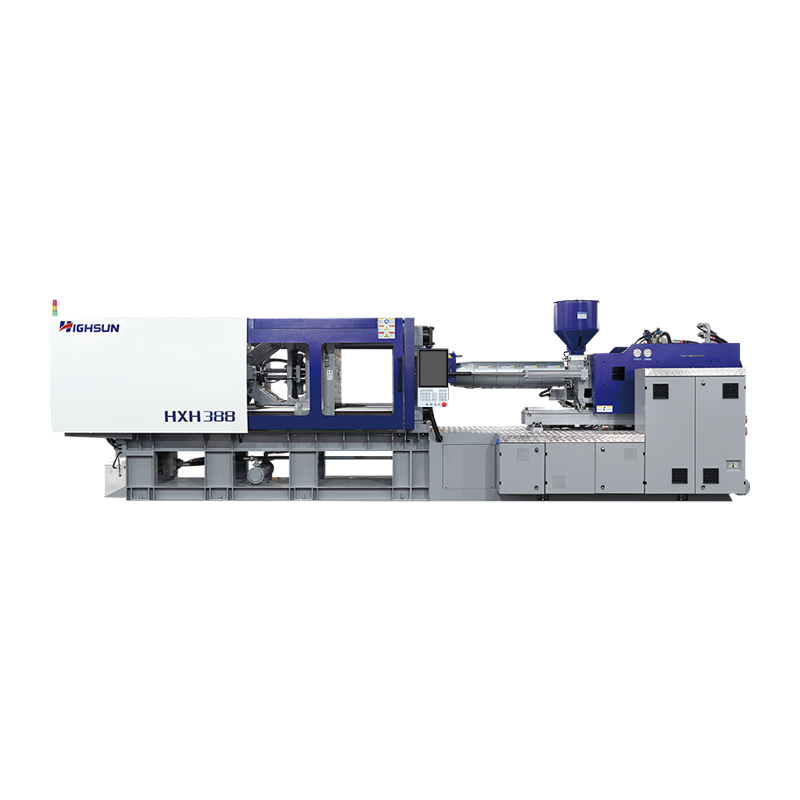 HXH388: HXH high-speed injection molding machine Suppliers, OEM/ODM Company - NiNingbo beilun highsun machinery Co., ltd is top HXH388: HXH high-speed injection molding machine suppliers and OEM/ODM company in China, ...View Product →
Energy consumption is another dimension of cycle optimisation. Servo-driven machines adjust the motor output to the actual load instead of running a fixed pump at full power. According to HIGHSUN's published technical documentation, the HXM servo series typically achieves 20–80% energy savings compared with fixed-pump hydraulic machines. The actual saving depends on the cooling share, mold size and cycle length; the chart below gives a representative comparison.
Representative mid-range figure within HIGHSUN's published 20–80% energy-saving range for servo-driven models. Actual savings depend on the part, mold and cycle conditions.
Process stability also depends on material preparation and production planning. Consistent pellet drying, feeding and mold temperature control reduce parameter corrections between cycles. In high-volume applications such as plastic logistics crates, consistency is part of the purchasing contract, so every stage of the process has to stay inside its window.
Injection Moulding Process Stages FAQ
What are the main stages of the injection moulding process?
The main stages are clamping, injection, holding pressure, cooling, mold opening and ejection. Post-processing and quality inspection follow the machine cycle.
What is an injection moulding machine and how does it work?
An injection moulding machine melts plastic granules, injects the melt into a closed mold, holds pressure to compensate for shrinkage, cools the part and then ejects it.
How long does an injection moulding cycle take?
Cycle time depends on wall thickness and material. Thin-wall parts can run in 10–20 seconds, while thick engineering plastic parts can take minutes. Cooling is typically the largest share.
What causes common injection moulding defects?
Short shots are usually injection pressure or material flow problems; flash indicates low clamping force; sink marks point to insufficient holding pressure; warpage is often caused by uneven cooling.
How do I choose the right injection moulding machine?
Match clamping force and shot size to the part, then verify injection pressure and speed. For PVC use a corrosion-resistant screw and barrel; for PET preforms choose a dedicated screw design.
How can I reduce injection moulding cycle time?
Improve mold cooling first because it dominates the cycle. Lower the melt temperature if quality allows, and use a servo or high-speed machine when injection and clamping are the bottlenecks.
 +86-188 6861 6288
 haixiong@highsun-machinery.com
 No.36 Yongjiang South Road, Beilun District. Ningbo City, 315800, China