 ENG
ENG  English
 русский
 Español
 Português
 عربى
عربى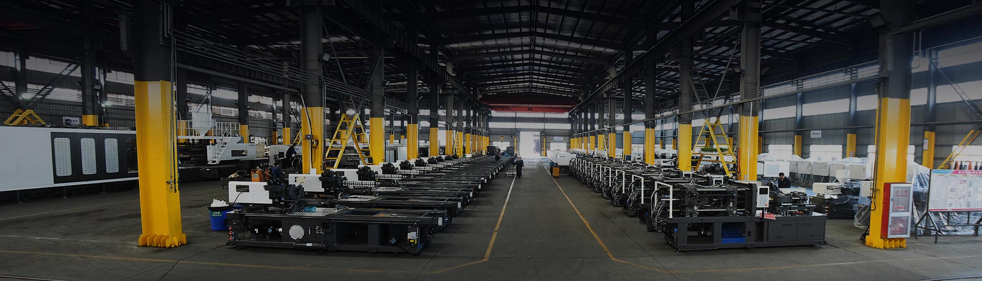
An injection moulding machine is an industrial manufacturing system that melts thermoplastic or thermosetting materials and injects the molten material under high pressure into a precision-engineered mold cavity, where it cools and solidifies into a finished plastic part. This process is one of the most widely used methods in modern manufacturing, accounting for over 32% of all plastic parts produced globally. The machine consists of three core systems: the injection unit, the clamping unit, and the mold — working together in a repeatable, high-speed cycle to produce complex, dimensionally accurate components at scale.
Whether you are evaluating injection molding equipment for a new production line or upgrading existing molding machines, understanding how these systems operate, what variables affect output quality, and how to select the right configuration is essential for maximizing efficiency and part consistency.
Content
- 1 How an Injection Moulding Machine Works: The Complete Cycle
- 2 Key Components of an Injection Moulding Machine
- 3 Types of Injection Moulding Machines
- 4 Materials Compatible with Injection Moulding Machines
- 5 Global Injection Moulding Industry: Market Trends and Growth
- 6 How to Select the Right Injection Moulding Machine for Your Application
- 7 Common Injection Moulding Defects and How to Prevent Them
- 8 About HIGHSUN Injection Moulding Machines
- 9 Frequently Asked Questions
How an Injection Moulding Machine Works: The Complete Cycle
The injection moulding process follows a precise sequential cycle. Each phase is critical to part quality, dimensional stability, and cycle efficiency. Modern injection molding machine designs have refined this cycle to achieve repeatability tolerances within ±0.01 mm on high-precision components.
The Six Stages of the Injection Moulding Cycle
- Clamping: The two halves of the mold are closed and locked under high clamping force, measured in tonnes (T), typically ranging from 98T to 3000T in industrial machines.
- Injection: Molten plastic is injected into the mold cavity at pressures between 70–140 MPa, filling the cavity within 0.5–5 seconds depending on part geometry.
- Dwelling (Packing): Additional material is packed into the cavity to compensate for volumetric shrinkage as the material cools.
- Cooling: The part solidifies inside the mold, typically the longest phase — accounting for 50–80% of total cycle time.
- Mold Opening: The clamping unit retracts, separating the mold halves.
- Ejection: Ejector pins push the finished part out of the cavity, completing the cycle.
Injection Moulding Cycle Phase Time Distribution (%)
The cooling phase dominates total cycle time, often accounting for 50–70% of each production cycle. Optimizing mold cooling channel design and coolant flow rate is one of the most effective ways to increase output on any injection molding machine. Engineers frequently use conformal cooling channels to reduce this phase by 15–30% compared to conventional straight-drill designs. Reducing cooling time directly translates to higher parts-per-hour throughput and lower energy cost per part.
Key Components of an Injection Moulding Machine
Every plastic mold machine shares a common architecture, though the engineering details and precision levels vary significantly between entry-level and high-performance industrial systems. The major sub-systems are:
Injection Unit
The injection unit is responsible for melting and delivering polymer material into the mold. It contains a hopper for raw material feed, a heated barrel, a reciprocating screw, and a nozzle. The screw simultaneously plastifies material (rotational motion) and injects it (linear motion). Shot size, injection speed, and back pressure are the critical process parameters controlled here.
Clamping Unit
The clamping unit holds the mold halves together against the injection pressure. Clamping force must exceed the projected area of the cavity multiplied by the cavity pressure — typically 0.3–0.5 T/cm². Industrial injection molding machines in heavy manufacturing range from 500T to 3000T clamping force for large automotive or industrial parts.
Mold for Injection Molding Machine
The mold for injection molding machine is a precision tool — typically machined from hardened steel or aluminum — that defines the final part geometry. A well-engineered mold includes runner systems, gate designs, venting, cooling circuits, and ejector mechanisms. Tooling life for hardened steel molds commonly exceeds 1,000,000 cycles.
Hydraulic and Electrical Drive Systems
Traditional machines use hydraulic drives; modern injection molding equipment increasingly uses all-electric or hybrid servo-hydraulic drives, offering 40–70% energy savings compared to conventional hydraulic systems. The choice between drive types has significant implications for precision, repeatability, and operating cost.
| Component | Primary Function | Key Specification |
|---|---|---|
| Injection Unit | Melt and inject polymer | Shot size (cm³), injection rate |
| Clamping Unit | Hold mold closed under pressure | Clamping force (T) |
| Mold / Tooling | Shape the final part geometry | Cavity count, cooling design |
| Screw & Barrel | Plastify and convey material | L/D ratio, screw diameter |
| Control System | Process monitoring and automation | PLC / HMI interface type |
Types of Injection Moulding Machines
Not all injection machine moulding systems are the same. The industry has evolved distinct machine architectures to meet specific material, production volume, and precision requirements. Understanding these types is essential when specifying injection molding machine and support machinery for a new facility or process upgrade.
Hydraulic Injection Moulding Machines
The most traditional configuration, powered entirely by hydraulic actuators. These machines offer high clamping forces and are well-suited for large, thick-walled parts. However, their energy consumption is higher than servo-driven alternatives, and response repeatability may be lower. Still widely used in applications where raw power and robustness outweigh energy costs.
Electric and Hybrid Servo-Hydraulic Machines
All-electric machines use servo motors for all machine movements, delivering exceptional repeatability (shot-to-shot variation under 0.1%), quiet operation, and energy savings of 40–70%. Hybrid machines pair a servo-driven pump with hydraulic actuators, achieving a balance between performance and cost. These represent the fastest-growing segment of the industrial plastic molding machine market globally.
Two-Platen Machines
Two-platen injection molding systems eliminate the rear platen found on standard toggle-clamp machines, significantly reducing machine footprint (by up to 30%) while enabling very large mold installations. Preferred for automotive bumpers, large containers, and multi-cavity tooling at high tonnage.
High-Speed Machines
Designed for thin-wall packaging, caps, and closures, high-speed molding machines can achieve cycle times below 3 seconds. They require specialized accumulators, rapid mold close/open sequences, and precision temperature control to maintain part quality at extreme throughput rates.
Multi-Color and Specialty Machines
Double-color (two-shot) machines, BMC (Bulk Moulding Compound) machines, PET preform machines, and PVC-specific systems are engineered for specific material and product requirements. These are specialized tools where the machine configuration is matched precisely to the material's rheological and thermal properties.
Machine Type Performance Comparison (Radar Chart)
This radar chart compares hydraulic versus electric/hybrid injection moulding machine configurations across six performance dimensions. Electric and hybrid systems score substantially higher in energy efficiency and precision, making them increasingly preferred in cleanroom electronics, medical device, and automotive precision part manufacturing. Hydraulic machines retain an advantage in raw clamping force for very large part production. For facilities running 3-shift operations, the energy and maintenance cost differential between machine types becomes a significant factor in total cost of ownership calculations.
Materials Compatible with Injection Moulding Machines
A major advantage of the injection moulding process is its material flexibility. Both standard commodity plastics and high-performance engineering polymers can be processed on properly configured injection molding machine systems. The key is matching barrel temperature profile, screw design, and residence time to the specific material's processing window.
Common Thermoplastics Processed
- Polypropylene (PP): Packaging, automotive interior, housewares. Processing temp: 200–280°C.
- Polyethylene (PE): Containers, caps, consumer goods. Processing temp: 150–240°C.
- ABS: Electronics housings, automotive trims, toys. Processing temp: 200–260°C.
- Nylon (PA): Gears, structural parts, connectors. Requires drying; processing temp: 230–290°C.
- PET: Preforms for beverage bottles. Requires specialized PET-series machines with appropriate screw design.
- PC / PC-ABS: Optical components, safety equipment, medical devices. Processing temp: 260–320°C.
Material Processing Temperature Ranges (°C)
Processing temperature is one of the most critical parameters when configuring a plastic mold machine for a new material. Running a material outside its processing window — either too hot or too cool — directly causes defects including degradation, short shots, or sink marks. Barrel temperature zones must be individually tuned from feed zone to nozzle to create the optimal melt profile. Materials such as PET and Nylon also require pre-drying to moisture levels below 0.02% to prevent hydrolytic degradation during processing, which would result in reduced molecular weight and brittle final parts.
Global Injection Moulding Industry: Market Trends and Growth
The global injection molding equipment market continues to expand, driven by demand from the automotive, packaging, medical device, consumer electronics, and construction sectors. Understanding market dynamics helps procurement and engineering teams time capital investment decisions effectively.
Global Injection Moulding Machine Market Size (USD Billion, 2019–2028)
The global injection moulding equipment market is projected to grow from approximately USD 16.8 billion in 2021 to over USD 35 billion by 2028, at a compound annual growth rate (CAGR) of roughly 8–9%. This expansion is primarily driven by electrification of the automotive industry (lightweight plastic component demand), growth in single-use medical devices, and rapid e-commerce packaging volume increases across Asia-Pacific markets. The shift toward electric and hybrid servo-hydraulic machine types is accelerating within this growth, as manufacturers prioritize lower energy costs and carbon footprint reduction targets in their capital equipment decisions.
Top Application Sectors
Injection Moulding Machine Market Share by End-Use Sector (%)
Packaging is the dominant application sector for plastic injection moulding machines globally, accounting for roughly one-third of all machine output by volume. The automotive sector is the second-largest consumer, with modern vehicles containing an average of 150–200 unique injection-moulded plastic components ranging from instrument panels to structural brackets. The medical device sector, while smaller by volume, demands the highest precision standards and is among the fastest growing, driven by demographic trends and increasing regulatory requirements for single-use sterile devices that eliminate cross-contamination risk.
How to Select the Right Injection Moulding Machine for Your Application
Selecting injection molding machine and support machinery is a multi-variable decision. Getting it wrong means underperforming equipment, excessive energy costs, or inability to hold dimensional tolerances. The following framework provides a systematic approach to specification.
Step 1: Define Clamping Force Requirements
Calculate projected cavity area (cm²) × cavity pressure (typically 300–500 bar) × safety factor (1.1–1.3). For example, a part with a 150 cm² projected area at 400 bar cavity pressure requires approximately 60–78 tonnes of clamping force. Always select a machine with at least 10–20% headroom above the calculated minimum.
Step 2: Determine Shot Size and Injection Capacity
The machine's shot size (in cm³ or grams) must accommodate the part weight plus runner/sprue weight at the intended material density. A common guideline is to run parts at 20–80% of the machine's maximum shot size for consistent process control. Running consistently at 95%+ of shot capacity risks material residence time issues and inconsistent fill.
Step 3: Evaluate Platen Size and Tie-Bar Spacing
The mold dimensions must fit within the machine's minimum/maximum daylight and tie-bar spacing. An oversized mold that cannot be properly clamped due to insufficient tie-bar clearance is a common and costly mistake in mold for injection molding machine specification.
Step 4: Match Drive Type to Production Requirements
For high-volume, thin-wall or precision parts, electric or hybrid machines are the preferred choice. For thick-section or large structural parts that require sustained high hydraulic force, conventional hydraulic machines remain competitive. Consider also the facility's power infrastructure, as large electric machines require stable, high-capacity power feeds.
| Application | Recommended Type | Clamping Range | Priority Factor |
|---|---|---|---|
| Thin-wall packaging | High-speed electric | 100–500T | Cycle time |
| Automotive structural | Two-platen hydraulic | 800–3000T | Clamping force |
| Medical devices | All-electric cleanroom | 50–300T | Precision / cleanliness |
| Multi-color parts | Two-shot / rotary | 200–1500T | Part complexity |
| General consumer goods | Servo-hydraulic hybrid | 100–800T | Energy efficiency |
Common Injection Moulding Defects and How to Prevent Them
Even a well-configured industrial plastic molding machine can produce defective parts if process parameters drift or the mold design has issues. Understanding the root causes of common defects is essential for process engineers and quality teams managing injection molding equipment.
Flash
Flash is excess plastic that flows into the parting line or around ejector pins, forming thin fins on the finished part. Primary causes include insufficient clamping force, excessive injection pressure or speed, a worn mold parting surface, or mold misalignment. Corrective actions include increasing clamping force, reducing injection pressure during the fill-to-pack transition, and inspecting/repairing the mold parting line.
Short Shots
Short shots occur when the mold cavity is not completely filled, resulting in an incomplete part. This is typically caused by insufficient material, too-low melt temperature, excessive cooling rate, or blocked gates/runners. Solutions include increasing shot size, raising barrel temperature, or redesigning the runner system for more balanced filling.
Sink Marks
Visible depressions on the part surface, particularly opposite thick walls or ribs, indicating the outer skin solidified before the core contracted fully. Increasing pack pressure and pack time, reducing wall thickness at problematic locations, and optimizing gate position relative to the thick section are the standard remedies.
Warpage and Dimensional Variation
Non-uniform cooling across the part creates differential shrinkage, resulting in warpage. Addressing this requires balanced cooling circuit design, uniform wall thickness in part geometry, correct material selection for target shrinkage rate, and optimized mold temperature control. Mold temperature uniformity within ±2°C across the mold surface is typically required for tight flatness tolerances.
Bubbles and Voids
Internal voids or surface bubbles result from trapped gas, material moisture, or insufficient packing. Ensuring proper material drying (to below recommended moisture content), improving mold venting, and increasing pack pressure are the primary corrective actions. For hygroscopic materials like Nylon and PC, inadequate drying is the single most common cause of bubble defects.
About HIGHSUN Injection Moulding Machines
Ningbo Highsun Plastic Machinery Co., Ltd. is headquartered in the Beilun Science & Technology Park in Ningbo — recognized as China's capital of plastics machinery. With a factory spanning over 120,000 square meters and nearly 20 years of rapid development supported by over 50 years of accumulated engineering expertise from its parent company, HIGHSUN has earned recognition as a Top 3 professional manufacturer of plastic injection molding machines in Ningbo and one of the Top 10 manufacturers of plastic molding machines in China.
HIGHSUN's product portfolio covers a comprehensive range of machine types — Electricity and Oil Hybrid Series, Two-Platen Series, High-Speed Series, Double-Color (Unmixed and Mixed), BMC Series, PET Series, and PVC Series — with clamping forces spanning from 98T to 3000T. Customized configurations are available to meet specific process and production requirements. Operating under the philosophy of "Pursuing Excellence, Molding Perfection," HIGHSUN remains focused on delivering refined production process management and high-performance outcomes for its global customer base.
Frequently Asked Questions
Q1: How does an injection moulding machine work?
An injection moulding machine works by melting plastic pellets in a heated barrel using a rotating screw, then injecting the molten material under high pressure into a closed mold cavity. The part cools and solidifies in the mold, after which the mold opens and ejector pins push out the finished component. The entire cycle — clamping, injection, cooling, and ejection — typically takes between 5 and 60 seconds depending on part size and complexity.
Q2: What materials can be used in injection moulding machines?
Most thermoplastics — including PP, PE, ABS, Nylon (PA), PET, PC, and PVC — can be processed on injection moulding machines with the appropriate screw design and barrel temperature settings. Thermoset materials such as BMC (Bulk Moulding Compound) and rubber compounds can also be processed on specialty machines configured for those materials. Material selection must consider the machine's temperature range, screw geometry, and corrosion resistance of barrel and screw materials.
Q3: How do I prevent flash in injection moulding?
Flash prevention requires ensuring the clamping force is sufficient to resist cavity pressure across the entire projected part area. Check mold parting surfaces for wear or contamination, reduce injection speed and pack pressure if they are excessively high, and verify mold alignment. Running a mold at the correct tonnage — not undersized — is the most reliable long-term solution. Routine mold maintenance and parting line inspection every 100,000–200,000 cycles also help prevent flash from developing as tooling wears.
Q4: What causes bubbles in injection moulded products?
Bubbles in injection moulded parts are most commonly caused by moisture trapped in insufficiently dried material — especially in hygroscopic resins like Nylon, ABS, or PC. They can also result from excessive melt temperature causing material degradation and gas generation, or from inadequate mold venting trapping air in the cavity. Solutions include verifying material drying conditions (target moisture below 0.02%), reducing barrel temperature in the front zones, and adding or cleaning vent slots in the mold at the last areas to fill.
Q5: What is the difference between a two-platen and three-platen injection moulding machine?
A three-platen (standard toggle) machine has a fixed platen, a moving platen, and a rear platen that anchors the toggle mechanism, making it longer overall. A two-platen machine eliminates the rear platen, with the clamping cylinders mounted directly on the moving platen — reducing the machine's footprint by up to 30% and allowing larger molds to be installed for the same clamping tonnage. Two-platen designs are preferred for high-tonnage applications where floor space and mold size are critical factors.
Q6: How much energy does an injection moulding machine consume?
Energy consumption depends heavily on machine type and tonnage. Conventional hydraulic machines typically consume 0.4–0.8 kWh per kg of processed plastic. All-electric machines typically consume 0.2–0.4 kWh/kg — roughly 40–60% less. For a facility running 10 machines on three shifts, this difference can represent tens of thousands of dollars in annual electricity savings. Servo-hydraulic hybrid machines offer an intermediate energy profile and are a practical upgrade path for facilities transitioning away from fully hydraulic systems.


 +86-188 6861 6288
 haixiong@highsun-machinery.com
 No.36 Yongjiang South Road, Beilun District. Ningbo City, 315800, China